Oscillator array with row and column control

a technology of oscillator array and row and column control, which is applied in pulse generators, pulse techniques, instruments, etc., can solve the problems of large chip area requirements, large amount of design and layout time, and negative effects of injection locking, so as to reduce the possibility of the effect of reducing the injection locking and coupling potential

Inactive Publication Date: 2007-06-19
GOOGLE LLC
View PDF11 Cites 16 Cited by
  • Summary
  • Abstract
  • Description
  • Claims
  • Application Information

AI Technical Summary

Benefits of technology

[0009]The present invention provides a circuit topology which can be used to create an array of individually tuned oscillators operating at different frequencies determined by common control inputs and an easily managed variation in design dimensions of several components. The result is an array of oscillators with minimal injection locking and coupling potential, minimal area, and greatly reduced design and layout time compared to prior art or conventional means.
[0011]Oscillators of different columns within the array may differ by a common setting of the selects to these oscillators and the physical ordering of the oscillators in the column to further reduce the possibility of injection locking. A base delay cell is provided with programmable strength which can be configured at a higher level in the physical hierarchy. This base delay element may be used with the oscillators of the array to provide selects to each column of oscillators such that each column may be programmed to operate at a different frequency from its neighbors.
[0012]In one exemplary embodiment, each column of oscillators is inverted in order from that of its neighboring columns. Thus, if a first column has oscillators that have 5 stages / 3 fanout, 5 stages / 4 fanout, 7 stages / 5 fanout, and 7 stages / 7 fanout, in that order, any neighboring column would have oscillators in the following order: 7 stages / 7 fanout, 7 stages / 5 fanout, 5 stages / 4 fanout, and 5 stages / 3 fanout. This arrangement of columns, as well as the differing selects input to each column of oscillators helps to assure that neighboring oscillators do not operate at frequencies that are similar to each other.
[0013]As a result, injection locking and coupling potential is minimized by this arrangement of oscillators. In addition, because each oscillator in the array of oscillators is identical in construction, the design and layout is simplified. Thus, design and layout time is minimized. The result of the circuit topology of the present invention is that each oscillator in the array of oscillators operates at a unique frequency that is not harmonically related to any other frequency of any other oscillator in the array. Since the ring oscillators truly operate independent of the other oscillators in the array, the array of ring oscillators according to the present invention provides a basis for obtaining a truly random number by sampling the frequency outputs of the array.

Problems solved by technology

One problem with some ring oscillator based random number generators, is that the sample frequency may be correlated to the ring oscillator frequency for a duration long enough to cause individual random number generator bits to be correlated and therefore, less random.
In many of these random number generators, negative affects of injection locking, large chip area requirements, and large amounts of design and layout time are experienced.

Method used


Image

  • Oscillator array with row and column control
  • Oscillator array with row and column control
  • Oscillator array with row and column control

Examples


Embodiment Construction

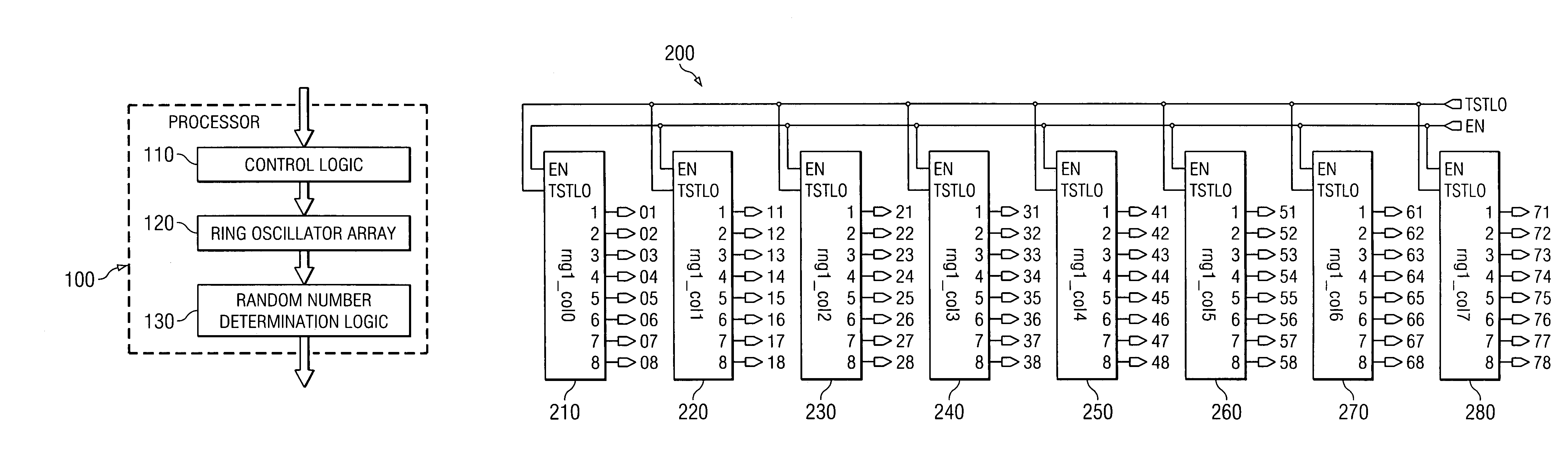
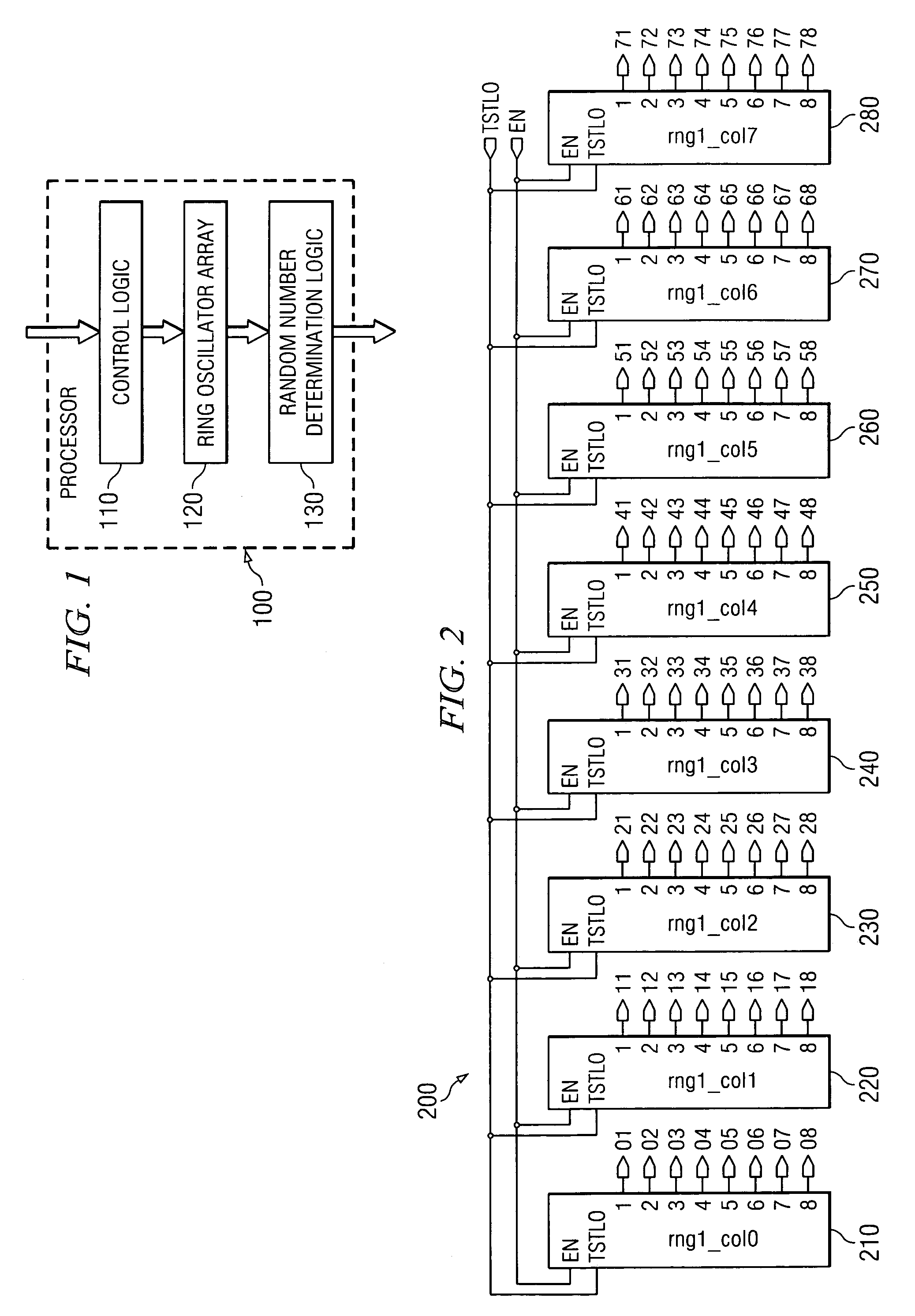
[0023]The present invention provides an array of independently operating free running ring oscillators that each generate a unique frequency output from those of the other oscillators in the array. Each oscillator is subject to substantial jitter. As a result, the oscillators in the array may provide a truly randomized source for generating random numbers. Other similar cryptographic applications or applications in which randomness is an important aspect of the application, may make use of the array of ring oscillators according to the present invention. For purposes of the present description, it will be assumed that the ring oscillators of the present invention are used to provide a source for generating random numbers in a random number generator.

[0024]It should be appreciated that while the following description provides exemplary embodiments that are directed to a ring oscillator array, the present invention is not limited to such. To the contrary, the oscillator array of the p...


PUM


Abstract

A circuit topology which can be used to create an array of individually tuned oscillators operating at different frequencies determined by common control inputs and an easily managed variation in design dimensions of several components is provided. An array of oscillators are provided arranged in columns and rows. Each oscillator in a column is unique from the other oscillators in the column based on number of stages in the oscillator and fanout so that each oscillator will operate at a unique frequency. Oscillators of different columns within the array may differ by a common setting of the selects to these oscillators and the physical ordering of the oscillators in the column to further reduce the possibility of injection locking. A base delay cell provides selects to each column of oscillators such that each column may be programmed to operate at a different frequency from its neighbors.

Description

BACKGROUND OF THE INVENTION[0001]1. Technical Field[0002]The present invention relates generally to an improved circuit topology for providing an array of individually tuned oscillators. More specifically, the present invention provides an oscillator array with row and column control that provides a plurality of individually tuned oscillators operating at different frequencies.[0003]2. Description of Related Art[0004]Random numbers are used in various encryption applications, which are particularly important in providing security for e-commerce applications as well as for a wide variety of other computer based or internet based communications and transactions. One approach to generating random numbers uses ring oscillators. In one approach using ring oscillators, a free running ring oscillator is used to clock a linear feedback shift register (LFSR). In another random number generator a single, slow voltage controller oscillator (VCO), which receives a noise input, samples the outpu...

Claims


Application Information

Patent Timeline
Patent Type & Authority Patents(United States)
IPC IPC(8): H03B29/00H03K3/03
CPCG06F7/588H03K3/0315H03K3/84
Inventor BOERSTLER, DAVID WILLIAMHAILU, ESKINDERHOFSTEE, HARM PETERLIBERTY, JOHN SAMUEL
Owner GOOGLE LLC
Why Eureka
Try Eureka