
Methods and apparatus for accessing data elements using improved hashing techniques

a data element and hashing technology, applied in the field of methods and apparatus for accessing data elements using improved hashing techniques, can solve the problems of imposing excessive resource burden, data block size is extremely cumbersome, and the cost of the data storage system is driven up, so as to reduce traffic and associated latencies, reduce the cost of the data storage system, and save tim

Active Publication Date: 2007-06-19
EMC IP HLDG CO LLC
View PDF5 Cites 30 Cited by
  • Summary
  • Abstract
  • Description
  • Claims
  • Application Information

AI Technical Summary

Benefits of technology

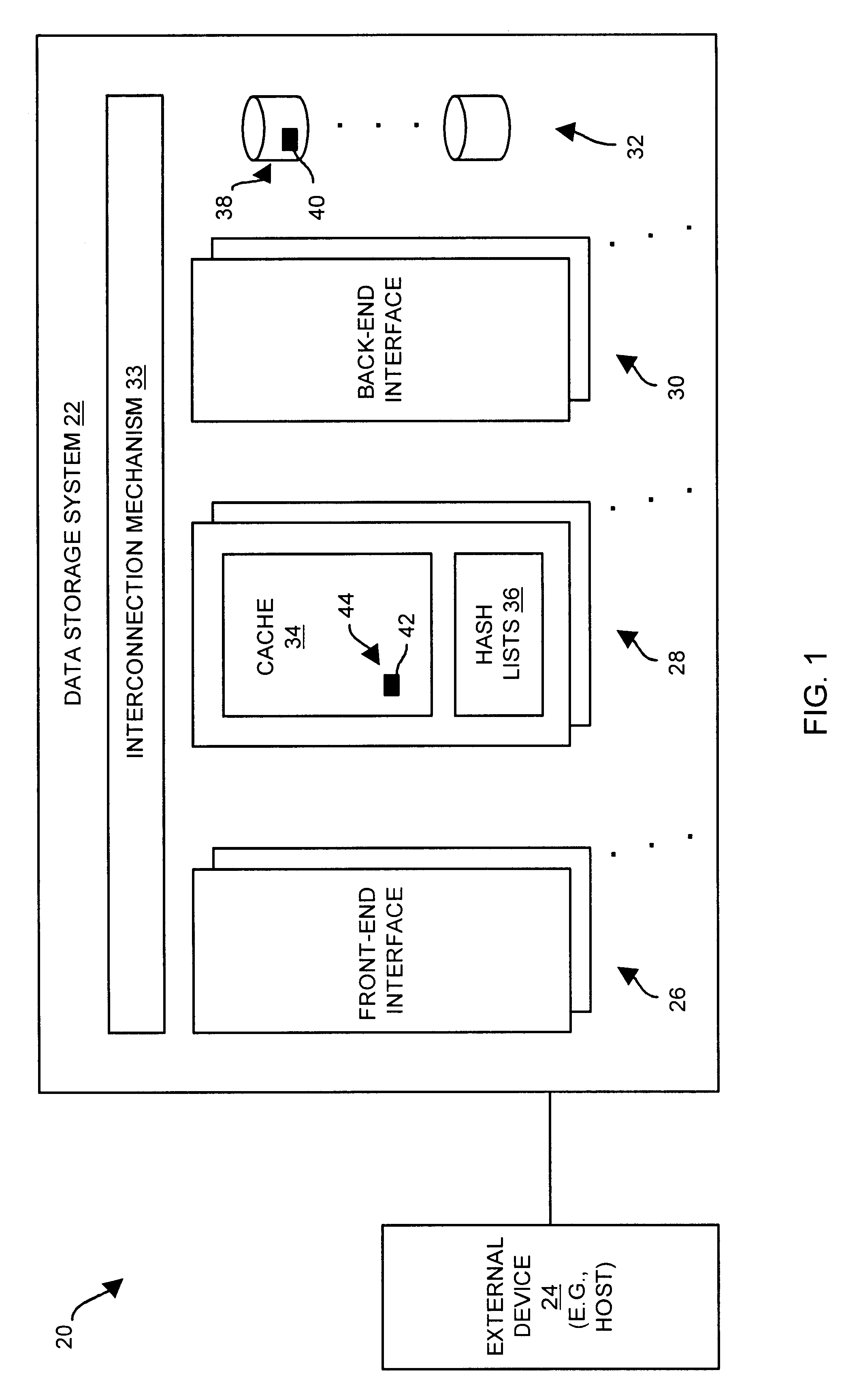
[0008]In contrast to the above-described conventional track table approach and the alternative single list of entries approach, embodiments of the invention are directed to techniques for accessing data elements (e.g., blocks of data) using a set of hash lists. The use of the set of hash lists alleviates the need for a track table that scales with the size of the set of disk drives as in the above-described track table approach, and requires less time to determine whether data blocks can be accessed from the cache compared to the above-described single list of entries approach. Furthermore, operations which access the set of hash lists can be performed within a set of memory circuit boards that stores the set of hash lists rather than another circuit board (e.g., a front-end interface circuit board) in order to, among other things, (i) provide superior performance, (ii) free the other circuit board to perform other tasks, and (iii) reduce traffic and associated latencies in the interconnection mechanism between the set of memory circuit boards and the other circuit board.
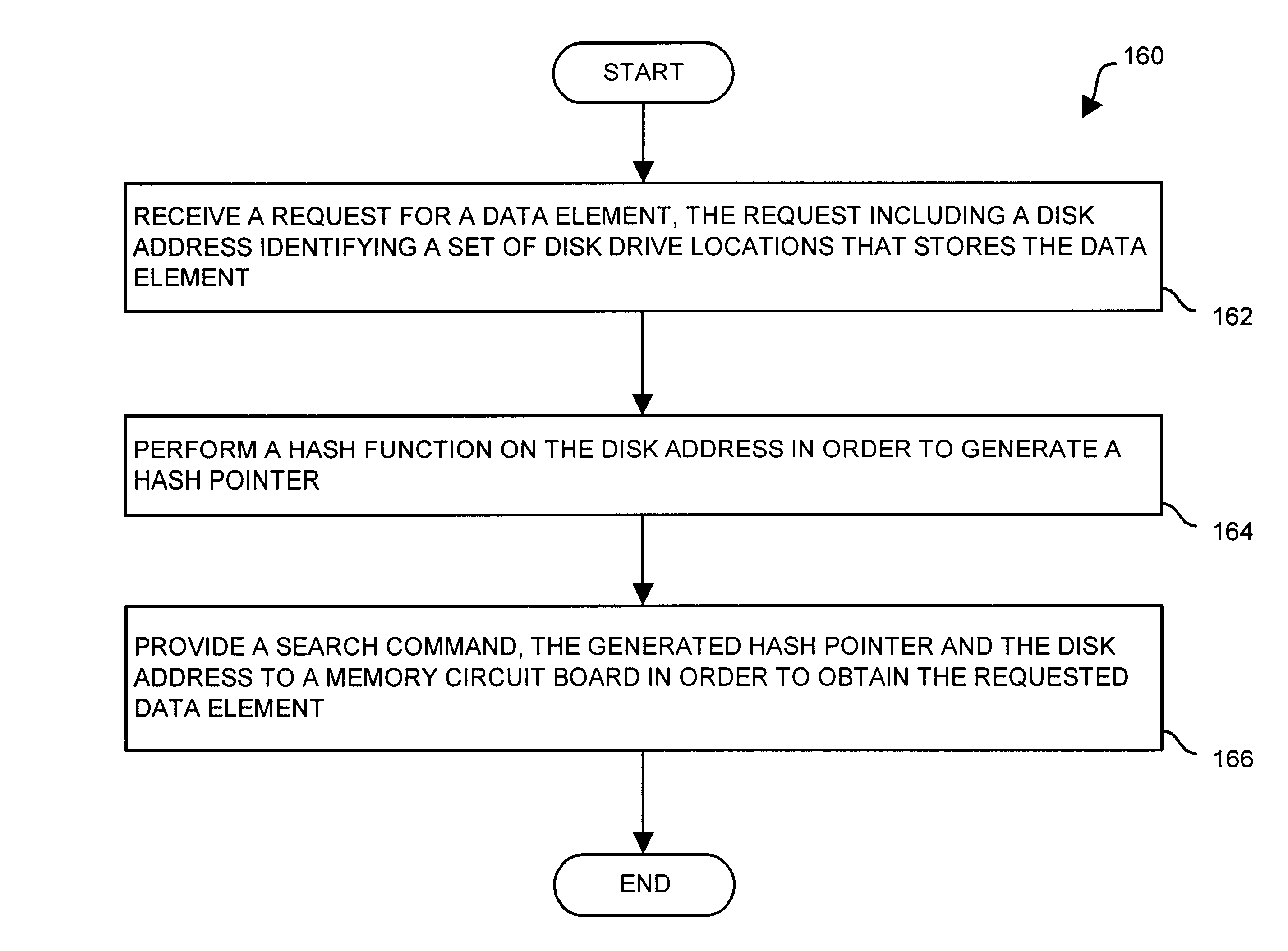
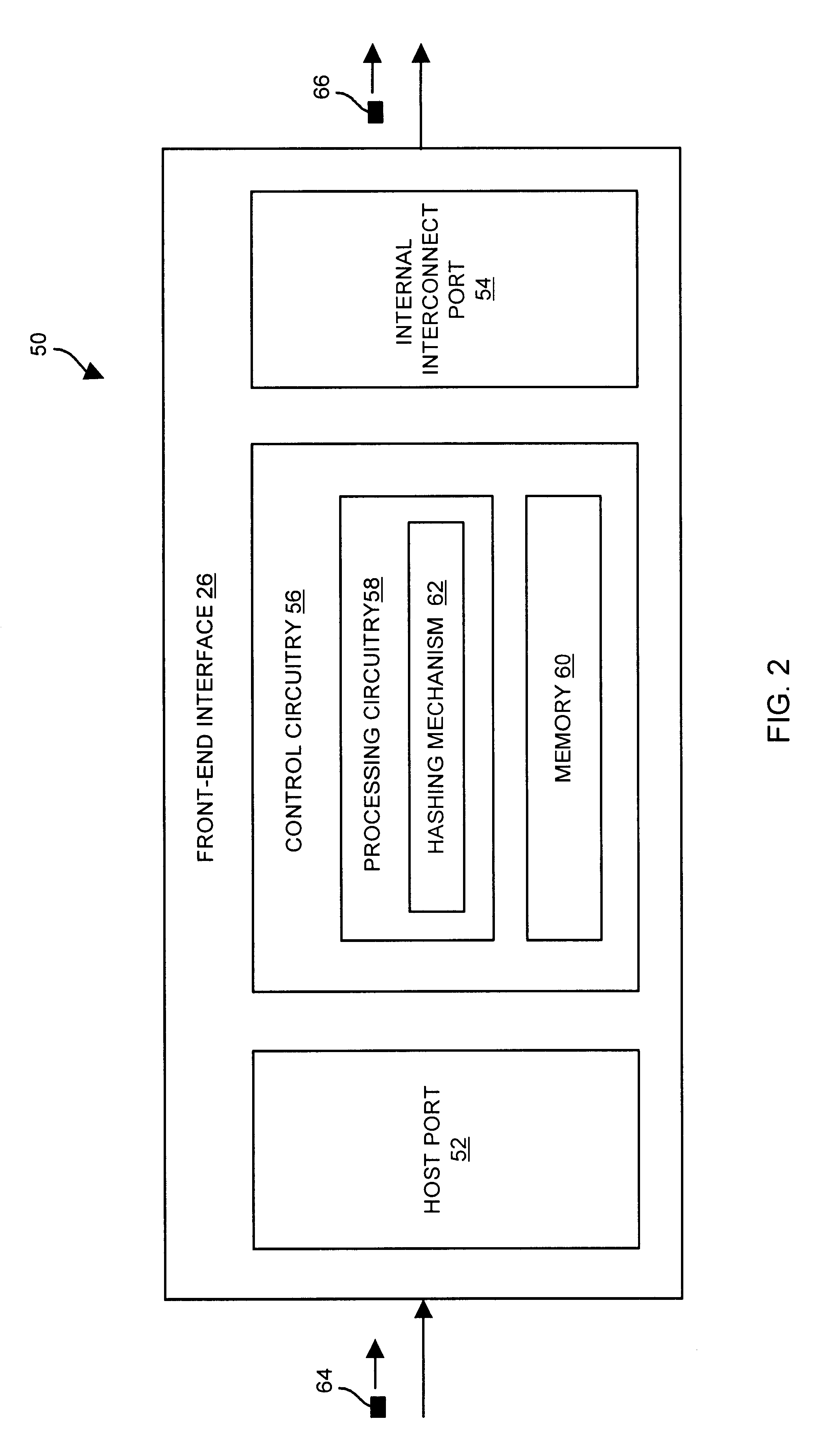
[0009]One embodiment is directed to a data storage system having a set of disk drives to store a data element, a set of memory circuit boards to store a set of hash lists and a cache, and a front-end interface coupled to the set of disk drives and the set of memory circuit boards. The front-end interface is configured to (i) receive a request for the data element, the request including a disk address identifying a set of disk drive locations that stores the data element, (ii) perform a hash function on the disk address in order to generate a hash pointer, and (iii) provide a search command, the disk address and the generated hash pointer to the set of memory circuit boards. The set of memory circuit boards is configured to (i) receive the search command, the disk address, and the hash pointer from the front-end interface, (ii) search the set of hash lists based on the hash pointer and the disk address, and (iii) provide an indication to the front-end interface indicating whether the set of hash lists includes an entry indicating that the data element resides in cache. The use of the hash function enables each hash list (i) to remain relatively short and (ii) to include caching information relating to only a portion of the cache. As such, a determination as to whether a data element resides in the cache can be made by simply searching one of the hash lists for quick response time. Furthermore, the burden of searching the hash list is on the set of memory circuit boards thus freeing both the front-end interface (e.g., to perform other operations) as well as the communications mechanism connecting the front-end interface with the set of memory circuit boards.
[0010]In one arrangement, the set of memory circuit boards is configured to search the set of hash lists by (i) selecting a hash list from the set of hash lists based on the hash pointer, each hash list including a set of entries, each entry including a disk address field; and (ii) determining whether the disk address of the request for the data element matches contents of the disk address field of an entry of the selected hash list in order to ascertain whether the set of hash lists includes an entry indicating that the cache stores the data element. The set of hash lists includes an entry indicating that the cache stores the data element when the disk address matches contents of the disk address field of an entry of the selected hash list. The set of hash lists does not include an entry indicating that the cache stores the data element when the disk address does not match contents of the disk address field of any entry of the selected hash list. Accordingly, the set of memory circuit boards does not need to search every entry in the set of hash lists, but only entries in the selected hash list until it finds an entry indicating that the cache stores the data element, or until it has searched the entire selected hash list (and has determined that the data element is not available in the cache) thus providing an acceptable response time.
[0011]In one arrangement, a second disk address identifies caching of a second data element. In this arrangement, the front-end interface circuit board is further configured to perform the hash function on the second disk address in order to generate a second hash pointer. Additionally, the set of memory circuit boards is further configured to add, to the set of hash lists, a second entry based on the generated second hash pointer and the second disk address. The second entry identifies the second data element. Accordingly, the set of memory circuit boards (rather than the front-end interface) can add entries to the set of hash lists thus freeing the front-end interface to perform other operations.
[0012]In one arrangement, the set of memory circuit boards is configured to add the second entry by selecting a hash list of the set of hash lists based on the second hash pointer, and attaching the second entry to the selected hash list. Preferably, the selected hash list is a linked list data structure, and one of the set of memory circuit boards is configured to attach the second entry by placing the second entry at a head of the linked list data structure. Placing the second entry at the head rather than the tail can simply involving inserting the second entry in front of the original head and avoid having to traverse the entire hash list. Furthermore, the oldest entry is at the tail and the newest entry is at the head thus enabling the data storage system to easily know which entries are the newest and oldest. For example, the set of memory circuit boards can be further configured to determine a number of entries in the selected hash list, and delete a third entry from the tail of the linked list data structure, i.e., selected hash list, when the number of entries in the selected hash list is greater than a predetermined limit. Accordingly, when selected hash list becomes excessively long, the least recently used entry can be removed from the selected hash list in order to conserve or limit the amount of memory space used by the hash list.

Problems solved by technology

Unfortunately, there are deficiencies to above-described conventional approach to providing data blocks based on a track table which includes an entry for every data block location available in a set of disk drives of a data storage system.
This demand for semiconductor memory, in addition to the semiconductor memory to be used as the I / O cache, is a substantial amount which not only drives the cost of the data storage system up, but imposes excessive resource burdens (e.g., higher power requirements, larger cabinets and cabinet footprints for holding the additional hardware, etc.).
That is, when the I / O cache is large, searching the entire single list in response to each request for a data block is extremely cumbersome (e.g., searching the single list of entries ties up the communications mechanism between the front-end interface and the I / O cache) and no longer delivers acceptable performance (e.g., response time).
Furthermore, the burden of searching the hash list is on the set of memory circuit boards thus freeing both the front-end interface (e.g., to perform other operations) as well as the communications mechanism connecting the front-end interface with the set of memory circuit boards.

Method used


Image

  • Methods and apparatus for accessing data elements using improved hashing techniques
  • Methods and apparatus for accessing data elements using improved hashing techniques
  • Methods and apparatus for accessing data elements using improved hashing techniques

Examples


Embodiment Construction

[0032]Embodiments of the invention are directed to techniques for accessing data elements (e.g., blocks of data) using a set of hash lists. The use of the set of hash lists alleviates the need for a conventional track table that scales with the size of the set of disk drives, and requires less time to determine whether data blocks can be accessed from the cache than searching a single list of entries that corresponds to every location within the cache. Moreover, operations which access the set of hash lists can be performed within a set of memory circuit boards that stores the set of hash lists rather than another circuit board (e.g., a front-end interface circuit board) in order to, among other things, (i) provide superior performance, (ii) free the other circuit board to perform other tasks, and (iii) reduce traffic in the interconnection mechanism between the set of memory circuit boards and the other circuit board and avoid latencies otherwise associated with such traffic.

[0033]...


PUM


Abstract

A data storage system has disk drives, memory circuit boards to store a set of hash lists and a cache, and a front-end interface. The front-end interface is configured to receive a data element request including a disk address identifying a set of disk drive locations that stores the data element; perform a hash function on the disk address in order to generate a hash pointer; and provide a search command, the disk address and the generated hash pointer to the memory circuit boards. The memory circuit boards are configured to receive the search command, the disk address, and the hash pointer from the front-end interface; search the set of hash lists based on the hash pointer and the disk address; and provide an indication to the front-end interface indicating whether the set of hash lists includes an entry indicating that the data element resides in cache.

Description

BACKGROUND OF THE INVENTION[0001]A typical data storage system includes an input / output (I / O) cache and a set of disk drives. The I / O cache is volatile storage (i.e., semiconductor memory) that temporarily buffers data transferred between an external device (e.g., a host) and the set of disk drives.[0002]One conventional data storage system further includes a front-end interface and a back-end interface. The front-end interface operates as an interface between the external device and the I / O cache by moving blocks of data (e.g., 512 byte sections) between the external device and the I / O cache. The back-end interface operates as an interface between the I / O cache and the set of disk drives by moving the data blocks between the I / O cache and the set of disk drives.[0003]Conventional data storage systems such as the one described above typically use a track table to determine whether data blocks, which reside in the set of disk drives, also reside in the I / O cache. For example, suppose...

Claims


Application Information

Patent Timeline
Patent Type & Authority Patents(United States)
IPC IPC(8): G06F12/02
CPCG06F12/0866G06F2212/284G06F2212/303
Inventor CHILTON, KENDELL A.
Owner EMC IP HLDG CO LLC
Learn More