Adaptive frequency variable delay-locked loop

a frequency variable and delay-locked loop technology, applied in the field of delay-locked loops, can solve the problems of narrow frequency locking or tracking range of dll, and limiting the overall frequency range of conventional delay-locked loops

Active Publication Date: 2007-06-26
NAT SEMICON CORP
View PDF10 Cites 60 Cited by
  • Summary
  • Abstract
  • Description
  • Claims
  • Application Information

AI Technical Summary

Benefits of technology

[0010]In one embodiment, the phase selection control loop generates the select signal to cause the multiplexer to select a delayed clock signal with an increased amount of delay relative to the currently selected delayed clock signal when the control voltage has a voltage level greater than a high threshold voltage. Moreover, the phase selection control loop generates the select signal to cause the multiplexer to select a delayed clock signal with a decreased amount of delay relative to the currently selected delayed clock signal when the control voltage has a voltage level less than a low threshold voltage. Finally, the phase selection control loop generates the select signal to cause the multiplexer to hold the currently selected delayed clock signal when the control voltage has a voltage level between the high threshold voltage and the low threshold voltage.

Problems solved by technology

However, the DLL has a major limitation associated with its narrow frequency locking or tracking range.
The conventional delay-locked loop lacks any significant frequency adjustment, thus limiting the overall frequency range of conventional delay-locked loops.
An important limitation of the conventional DLL architecture of FIG. 1 is that the conventional DLL has a limited frequency locking range.

Method used


Image

  • Adaptive frequency variable delay-locked loop
  • Adaptive frequency variable delay-locked loop
  • Adaptive frequency variable delay-locked loop

Examples


Embodiment Construction

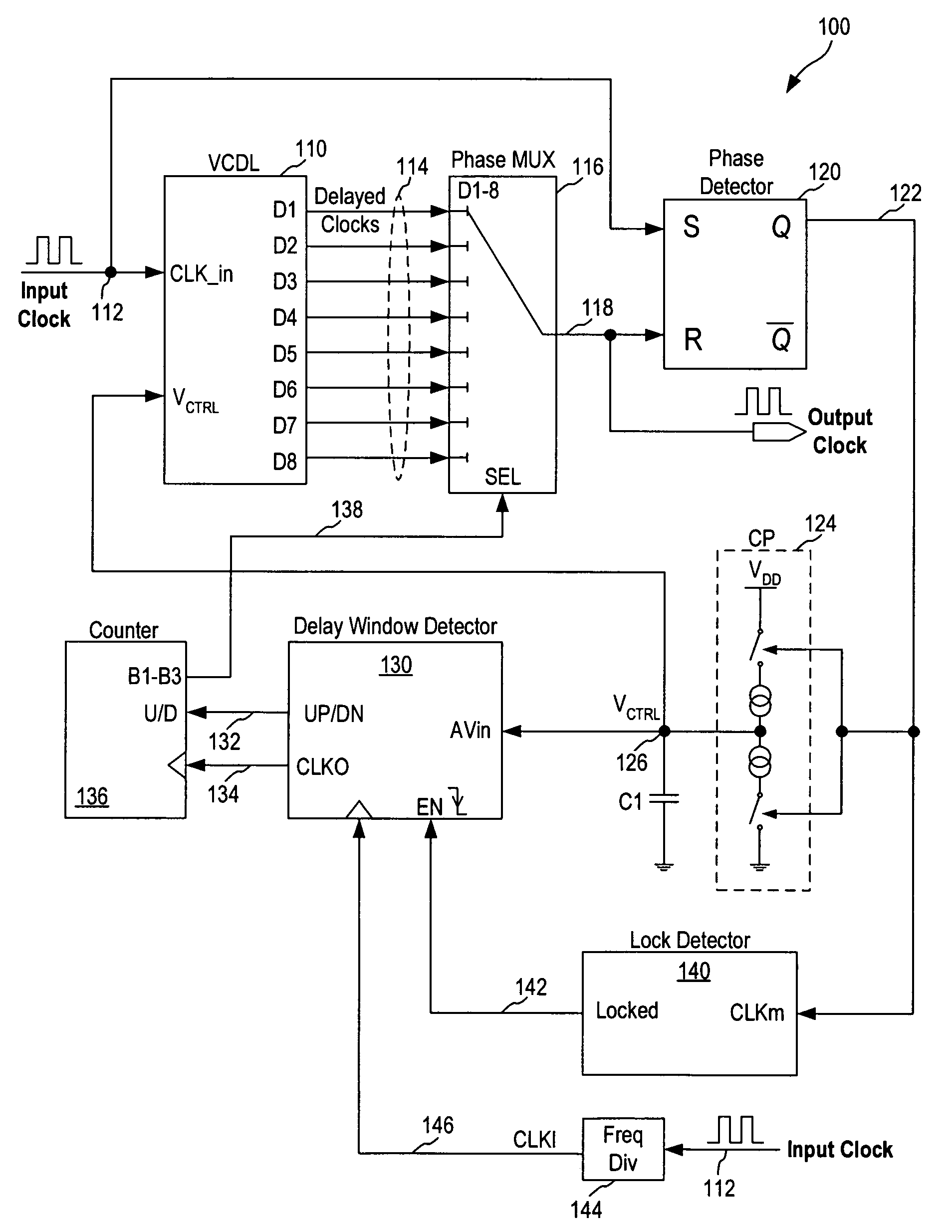
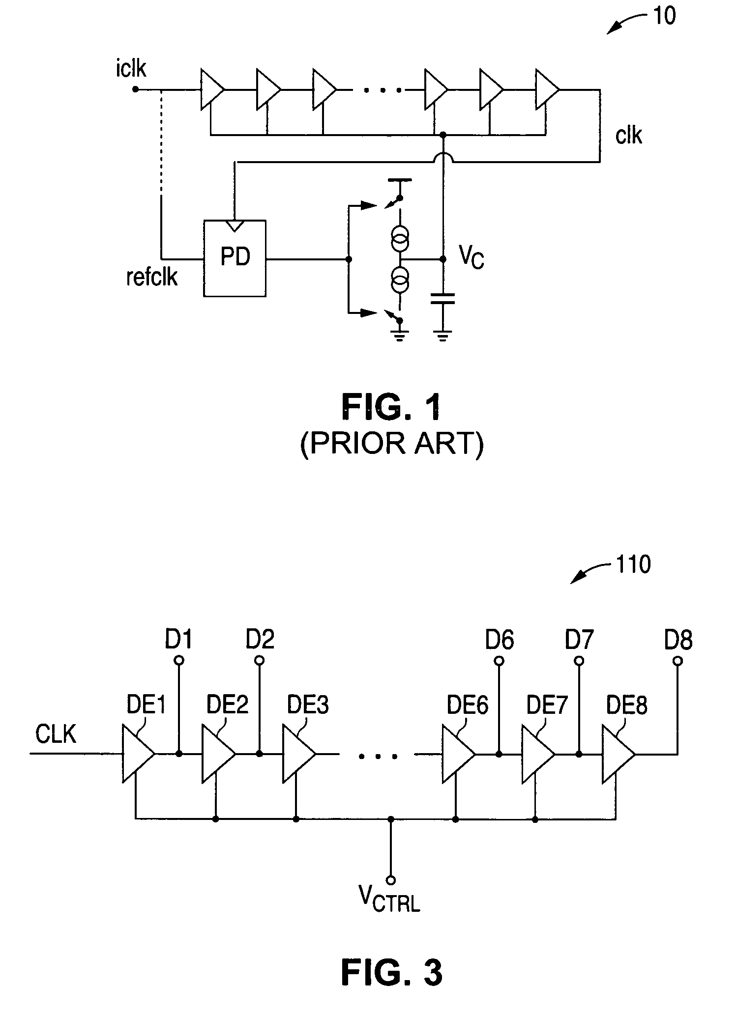
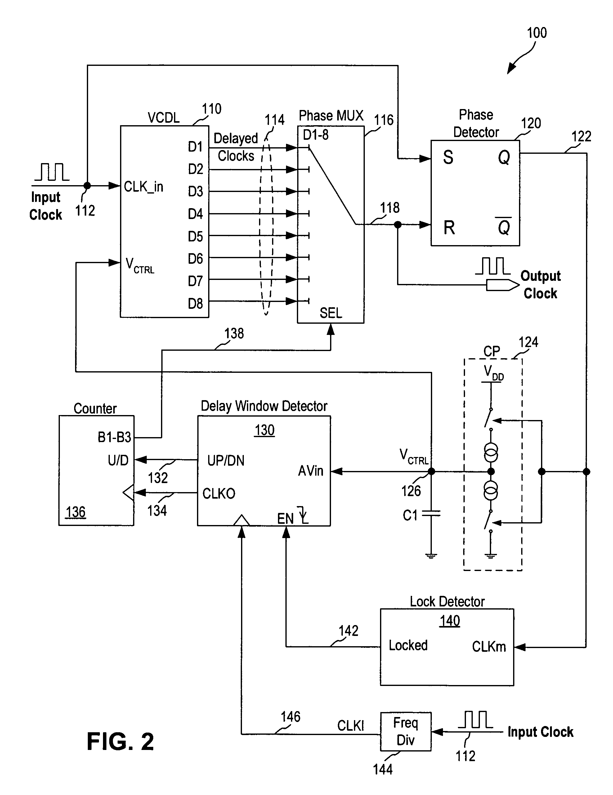
[0022]In accordance with the principles of the present invention, a delay-locked loop (DLL) includes a voltage controlled delay line (VCDL) receiving an input clock signal and generating multiple clock phases as a set of delayed clock signals and a clock phase multiplexer selecting one of the delayed clock signals as the output clock signal for the DLL. The DLL includes a phase selection control loop to select one of the delayed clock signals based on the amount of delay required and a phase detection control loop to adjust the phase error within the selected clock phase so as to lock the delay of the selected delayed clock signal to the input clock signal. By incorporating the phase selection control loop and the phase detection control loop in the DLL, the DLL of the present invention can achieve a wide frequency locking range while providing excellent jitter performance.

[0023]In one embodiment, the phase detection control loop generates a control voltage for the VCDL for adjustin...


PUM


Abstract

A delay-locked loop circuit receiving an input clock signal and generating an output clock signal whose delay is locked to the input clock includes a voltage controlled delay line (VCDL), a multiplexer, a phase detection control loop and a phase selection control loop. The VCDL generates a set of multi-phase delayed clock signals. The multiplexer selects one of the delayed clock signals as the output clock signal based on a select signal. The phase detection control loop measures the phase difference between the input and output clock signals and generate a control voltage for driving the VCDL. The phase selection control loop measures the control voltage and generates the select signal based on the control voltage, causing the multiplexer to select a delayed clock signal with increased or decreased amount of phase delay relative to the currently selected delayed clock signal or to hold the currently selected delayed clock signal.

Description

FIELD OF THE INVENTION[0001]The invention relates to delay-locked loops and, in particular, to a delay-locked loop that can track a wide frequency range.DESCRIPTION OF THE RELATED ART[0002]Clock signals are used in electronic systems to control the timing and processing of various operations. It is often necessary to synchronize the clock signals that are distributed to several integrated circuits within an electronic system to ensure proper operation. Phase-locked loop (PLL) and delay-locked loop (DLL) are two circuits that are widely used for clock regeneration in electronic systems so as to synchronize the local clock on each integrated circuit to the desired reference circuit.[0003]In the phase-locked loop, a voltage-controlled oscillator produces a local clock. The phases of the local clock and a reference clock are compared by a phase-frequency detector, with the resulting error signal used to drive the voltage-controlled oscillator via a loop filter. The feedback via the loop...

Claims


Application Information

Patent Timeline
Patent Type & Authority Patents(United States)
IPC IPC(8): H03L7/06
CPCH03L7/0812H03L7/0814H03L7/10H03L7/0818H03L7/0816
Inventor CHOI, DONG-MYUNG
Owner NAT SEMICON CORP
Why Eureka
Try Eureka