

Method and arrangement for noise rejection in a receiver circuit
a receiver circuit and receiver technology, applied in the direction of transmission, electromagnetic transmission, transmission monitoring, etc., can solve the problem of limited quality reduction time duration
- Summary
- Abstract
- Description
- Claims
- Application Information
AI Technical Summary
Benefits of technology
Problems solved by technology
Method used
Image

Examples
Embodiment Construction
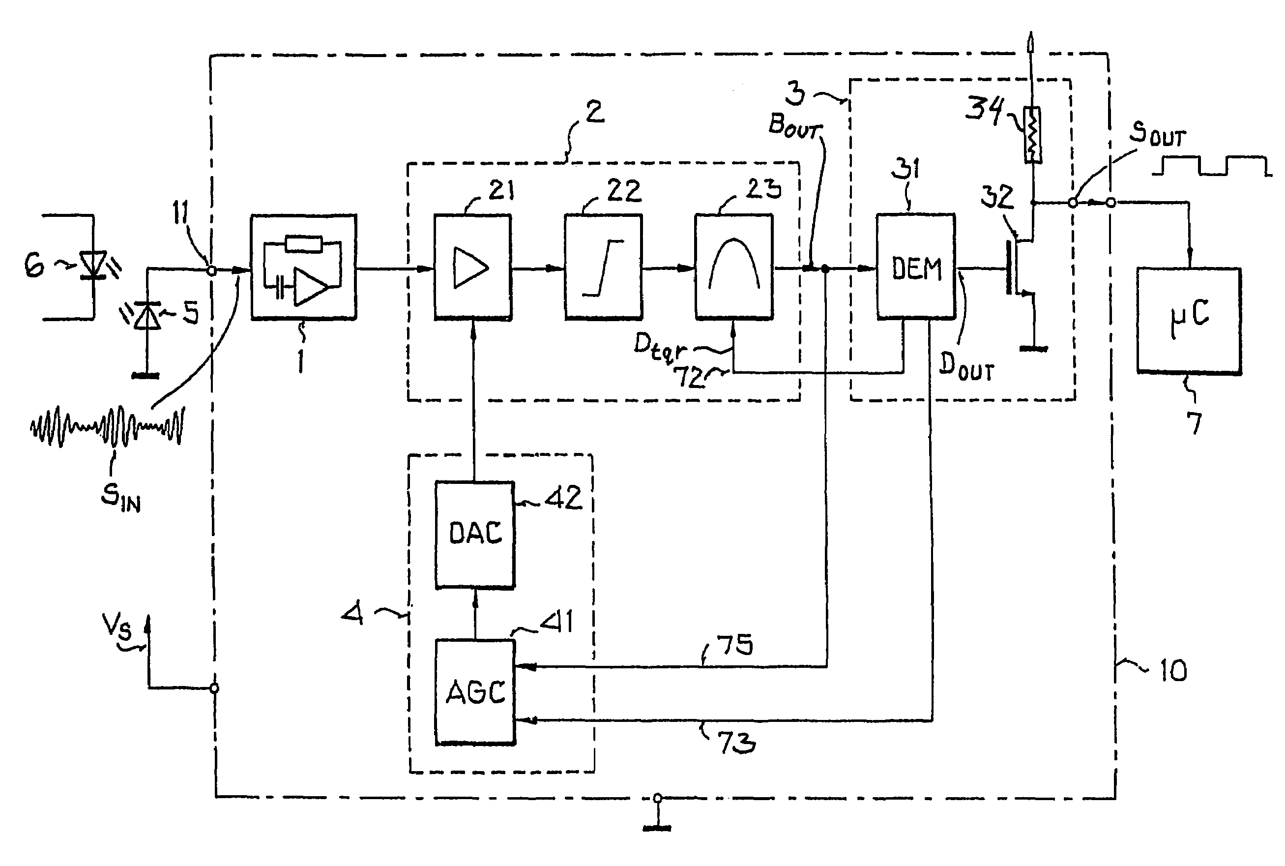
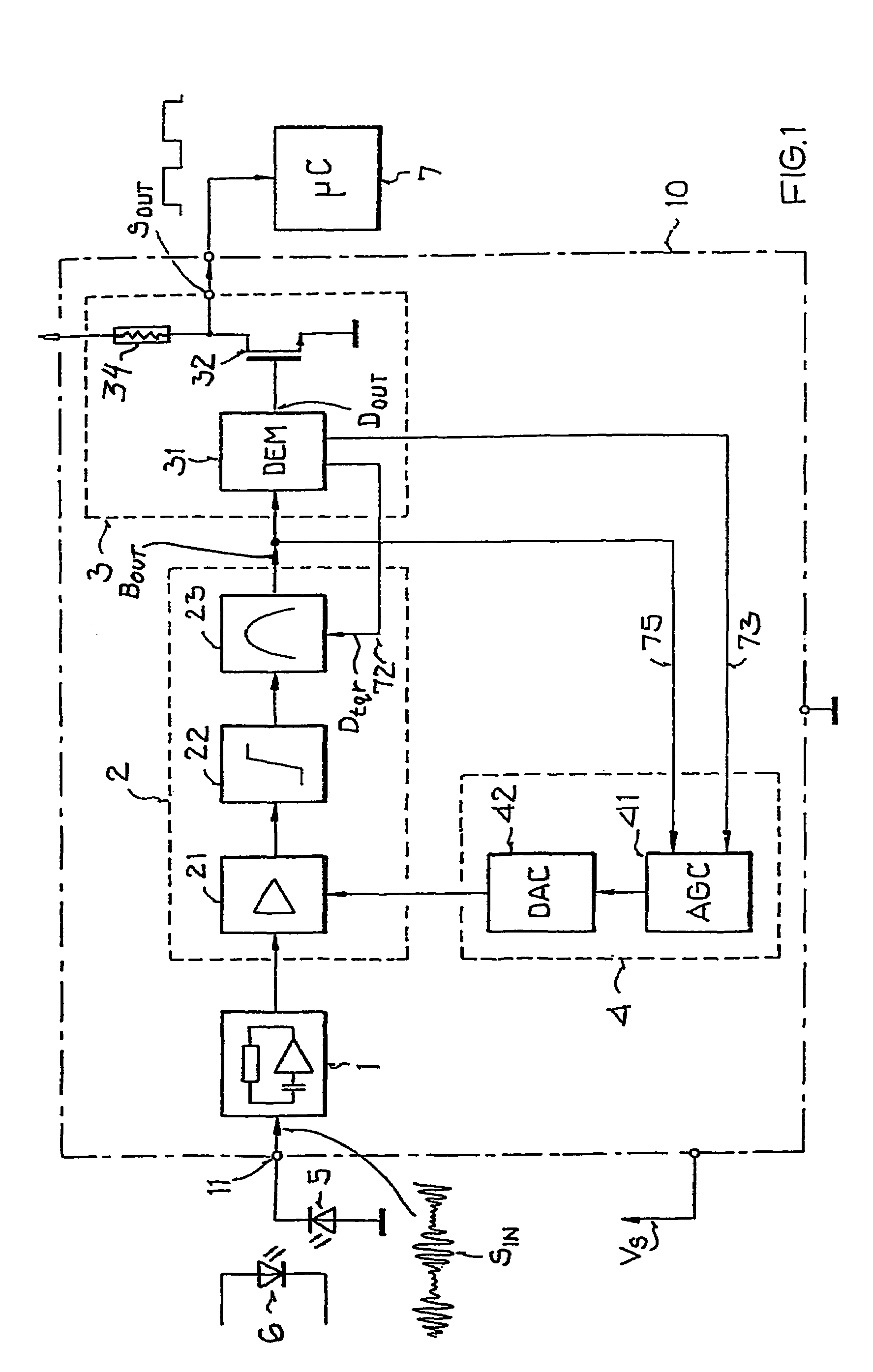
[0021]FIG. 1 shows a block diagram of a receiver circuit 10 and its surrounding environment. The carrier-modulated data radiated or emitted by an optical transmitting diode 6 are received as infrared pulse packets by a photodiode 5. These infrared pulse packets with a carrier frequency of e.g. 38 kHz, which impinge on the photodiode 5, are converted into electrical current signals SIN. They are present at the input terminal or connection 11 of the receiver circuit 10. These electrical current signals SIN are provided to an input circuit 1 functioning as a transimpedance amplifier, which amplifies the current signals SIN and converts them into voltage signals. In this context, the converted voltage must be large enough to make the noise component negligible in the following signal processing stages. In the following signal preparation or processing element 2, these voltage signals are again amplified by means of a regulating amplifier 21, limited by means of a limiter 22, and then fi...
PUM
 Abstract
Description
Claims
Application Information