Device for performing laser angioplasty with OCT monitoring

a laser angioplasty and monitoring device technology, applied in the field of laser angioplasty, can solve the problems of increasing the risk of laser being applied to the wrong place, difficult for medical staff to distinguish between plaque and vascular wall, and coronary arteries,

Active Publication Date: 2007-07-03
SIEMENS HEALTHCARE GMBH
View PDF10 Cites 44 Cited by
  • Summary
  • Abstract
  • Description
  • Claims
  • Application Information

AI Technical Summary

Benefits of technology

[0009]The interventions described above are implemented using an angiography device under x-ray monitoring by means of contrast media. The drawback of this method is that the coronary arteries are only shown in two dimensions and only the actual stenosis is shown on the x-ray image. During the intervention it is difficult for medical staff to distinguish between plaque and vascular wall. This increases the risk of the laser being applied to the wrong places, resulting in injury in the form of hemorrhage, damage or perforation / dissection of the vascular wall.
[0016]The integration, according to the invention, of a laser angioplasty catheter with an OCT (Optical Coherence Tomography) catheter into a single module produces an optimum system for reducing vascular stenoses. The great advantage of this combined catheter lies in the reduction in process stages and in the catheters used. At the same time, a lower x-ray level is required to monitor the catheter implementation. The OCT system images provide important additional medical information with high resolution, particularly at close range over the plaque and the vascular wall. This means that the plaque can be identified, and can be removed by using the laser probe in the right locations with the right amount of energy, and the success of the procedure can then be checked immediately. This combined device thus significantly reduces the known risks of such an intervention.
[0017]The OCT sensor, which is preferably configured as a revolving mirror, may be located both in front of and behind the laser radiation device when viewed from the external end of the catheter, whereby the arrangement in front of the laser radiation device has the advantage that the drive shaft for the OCT sensor does not have to be run right through the laser radiation device, said drive shaft being preferably configured as a hollow, flexible drive shaft which also accommodates the OCT signal lines, which are configured as glass fiber lines. If the drive shaft did have to go right through the laser radiation device, this would potentially create problems if said radiation device is a radiating lens which is connected to an external laser light source via an optical fiber line.
[0018]The running of the drive shaft through the laser radiation device presents no difficulties, however, if said laser radiation device comprises an outwardly radiating diode array, preferably ring-shaped and circumferential, which is connected to an external control circuit via electrical connection lines. In this case, therefore, it is not external laser light that is fed in, but the laser light that is generated by the laser diode array at the radiation point of the catheter tip. By selectively controlling the individual laser diodes as appropriate, a beam can be aimed in just one specific direction so that plaque deposits can be irradiated completely selectively without simultaneous irradiation of an inner vascular wall that is not coated with plaque.
[0021]Finally, the invention also makes provision for an inflatable and preferably multi-chambered balloon, which is used for fixing the catheter and / or for vascular dilatation, to be disposed on the catheter tip. This balloon may be used both for fixing the catheter tip in a required location during the intervention or for additional dilatation of the vessel, thus providing additional mechanical means for breaking up of plaque deposits.

Problems solved by technology

The drawback of this method is that the coronary arteries are only shown in two dimensions and only the actual stenosis is shown on the x-ray image.
During the intervention it is difficult for medical staff to distinguish between plaque and vascular wall.
This increases the risk of the laser being applied to the wrong places, resulting in injury in the form of hemorrhage, damage or perforation / dissection of the vascular wall.
The introduction of an IVUS (intravascular ultrasound) catheter into the vessel enhances the imaging information, yet has the disadvantage that a relatively expensive catheter must also be inserted into the patient and must be removed from the vessel before the balloon catheter is inserted.
The disadvantage of the IVUS solution lies in the limited local resolution of the ultrasound method.

Method used


Image

  • Device for performing laser angioplasty with OCT monitoring
  • Device for performing laser angioplasty with OCT monitoring

Examples


Embodiment Construction

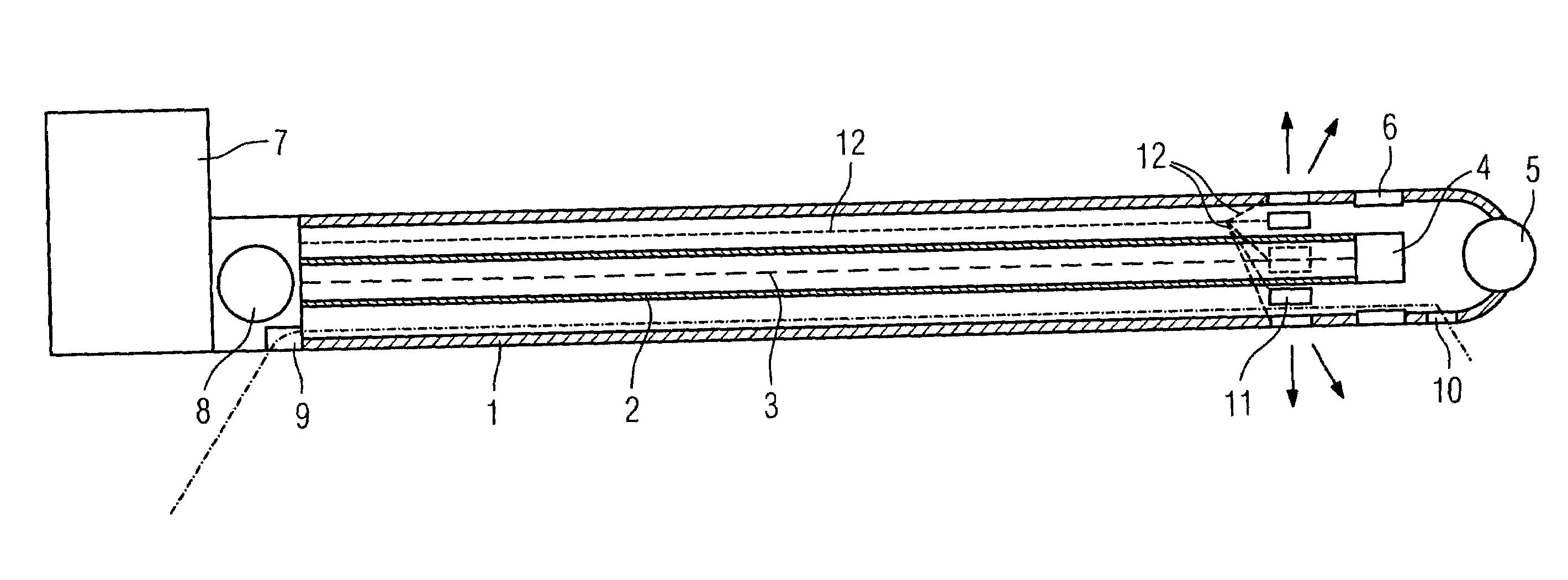
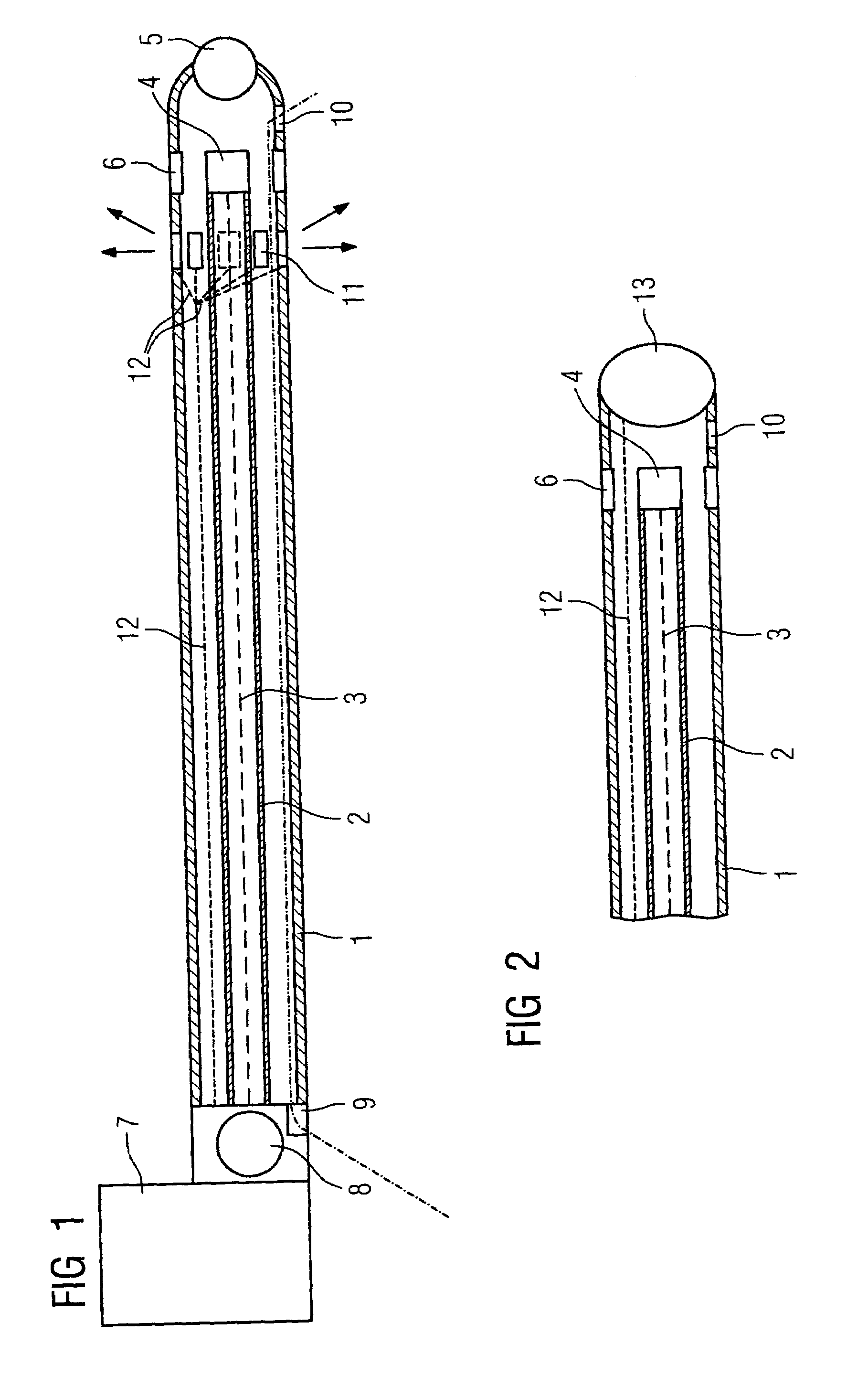
[0025]FIG. 1 is a schematic diagram of a combined OCT laser angioplasty catheter with an outer, flexible catheter sheath 1, inside which is disposed a hollow, flexible drive shaft 2 with integrated glass fiber line 3 as the OCT line. The hollow, flexible drive shaft is used for driving a rotating mirror 4 which forms the OCT sensor, said rotating mirror being disposed in the catheter tip behind a balloon 5 used for fixing the catheter and / or for vascular dilatation. The rotating mirror 4 is located inside a ring-shaped, circumferential output window 6 for the infrared light with which the inner vascular wall is irradiated and which is fed in via the signal lines 3, whereby the reflected light is fed back through the same line and processed at the external end of the catheter in an appropriate evaluation device 7. A rotating coupling for the connections is shown at 8, while 9 represents an inlet opening for feeding in contrast media and irrigation fluid which is transported forward i...


PUM

PropertyMeasurementUnit
distanceaaaaaaaaaa
flexibleaaaaaaaaaa
areaaaaaaaaaaa

Abstract

Device for performing laser angioplasty, in which laser light is beamed via a laser radiation device in the area of a catheter tip, with simultaneous OCT monitoring, for the ablation of plaque. The feed lines for the laser radiation device and the rotating OCT signal lines are disposed in a common catheter sheath, said feed lines leading to an OCT sensor disposed within a ring-shaped window running around the circumference of the catheter sheath, said OCT sensor being disposed at a distance from the laser radiation device.

Description

CROSS REFERENCE TO RELATED APPLICATIONS[0001]This application claims priority to the German application No. 10 2004 008 366.5, filed Feb. 20, 2004 which is incorporated by reference herein in its entirety.FIELD OF INVENTION[0002]The invention relates to a device for performing laser angioplasty, in which laser light is beamed via a laser radiation device in the area of a catheter tip, with simultaneous OCT monitoring, for the ablation of plaque, whereby the feed lines for the laser radiation device and the OCT signal lines are disposed in a common catheter sheath.BACKGROUND OF INVENTION[0003]Vascular disease, in particular cardiac infarction, is one of the most common fatal illnesses. It is caused by diseases of the coronary arteries (arteriosclerosis), in which the build-up of deposits (arteriosclerotic plaque) causes occlusions in the coronary arteries.[0004]Nowadays, if coronary angiography reveals serious stenoses in the coronary arteries, causing angina pectoris which restricts...

Claims


Application Information

Patent Timeline
Patent Type & Authority Patents(United States)
IPC IPC(8): A61B18/22A61B18/24G01N21/17A61B1/00A61B10/00A61B17/00A61B18/20A61B19/00A61F2/958A61M25/00
CPCA61B18/24A61B2017/00057A61B2019/2253A61B34/73
Inventor MASCHKE, MICHAEL
Owner SIEMENS HEALTHCARE GMBH
Why Eureka
Try Eureka