Hydrocratic generator

a generator and hydropower technology, applied in the direction of motors, sea energy generation, electrical equipment, etc., can solve the problems of increasing the latent energy or enthaly of evaporated water, the production of enormous amounts of inexpensive electrical power, and the hydropower plant typically costs about $10 per megawatt hour to produce. , to achieve the effect of efficient exploiting the osmotic energy potential

Inactive Publication Date: 2007-07-03
WADER
View PDF18 Cites 44 Cited by
  • Summary
  • Abstract
  • Description
  • Claims
  • Application Information

AI Technical Summary

Benefits of technology

[0018]Accordingly, it is an aspect to provide an improved apparatus and method for generating power using a novel forward osmosis process which efficiently exploits the osmotic energy potential between two bodies of water having different salinity concentrations.
[0019]Advantageously, the method and apparatus of the present invention does not require the use of a semi-permeable membrane or other specially formulated material, nordoes it require heating or cooling of the fresh water or salt water solution. Moreover, the present invention may recover energy from a wide variety of fresh water sources, including treated or untreated river run-off, treated waste-water run-off or effluent, storm-drain run-off, partly contaminated fresh water run-off, and a wide variety of other fresh water sources. Thus, the present invention is well suited to large scale power production in a wide variety of geographic locations and under a wide variety of conditions. The invention has particular advantage for use in remote regions where electrical power generation by conventional means may be commercially infeasible or impractical.

Problems solved by technology

In the Northwest, for example, electricity from hydropower plants typically costs about $10 per megawatt hour to produce.
Cooling causes the water vapors to condense into clouds, ultimately resulting in precipitation.
This absorbed energy causes a concomitant increase in the latent energy or enthalpy of the evaporated water.
If this source of latent stored energy could somehow be efficiently exploited, it could result in the production of enormous amounts of inexpensive electrical power from a heretofore untapped and continually renewable energy resource.
While such systems may have useful application on a small scale under certain limited conditions, full-scale commercial development and exploitation of such power-generation systems is hampered by the large membrane surface area required to achieve adequate flow rates and the expense and difficulty of maintaining such semi-permeable membranes.
Although modern advances in synthetic materials have produced membranes that are very efficient at rejecting brine solutes and are tough enough to withstand high pressures, such membranes are still susceptible to clogging, scaling and general degradation over time.
For example, river water used as a fresh-water source would likely carry a variety of solutes and other suspended sediment or contaminants which could easily clog the membrane, requiring filtering and / or periodic cleaning.
Treated effluent from a municipal waste-water treatment plant used as a fresh water source would present similar and possibly additional complications, making such approach commercially impractical.
While such a system demonstrates the usefulness of the general approach, the proposed system utilizing bio-elastomer elements or the like is not readily suited for large-scale, low cost energy production.
Again, the exposed surface area would be subject to contamination and degradation over time, as with the membranes discussed above, making such a system prohibitively expensive to construct and maintain.
While this approach generally avoids the membrane and large surface area contamination problems discussed above, it is not ideally suited for large-scale, low cost energy production.
This is because of the number and complexity of components involved and the need to heat and cool the fresh water in pressure sealed evaporator and condenser units.
Such a system would be expensive to construct and operate on a commercial scale.

Method used


Image

  • Hydrocratic generator
  • Hydrocratic generator
  • Hydrocratic generator

Examples


example 1

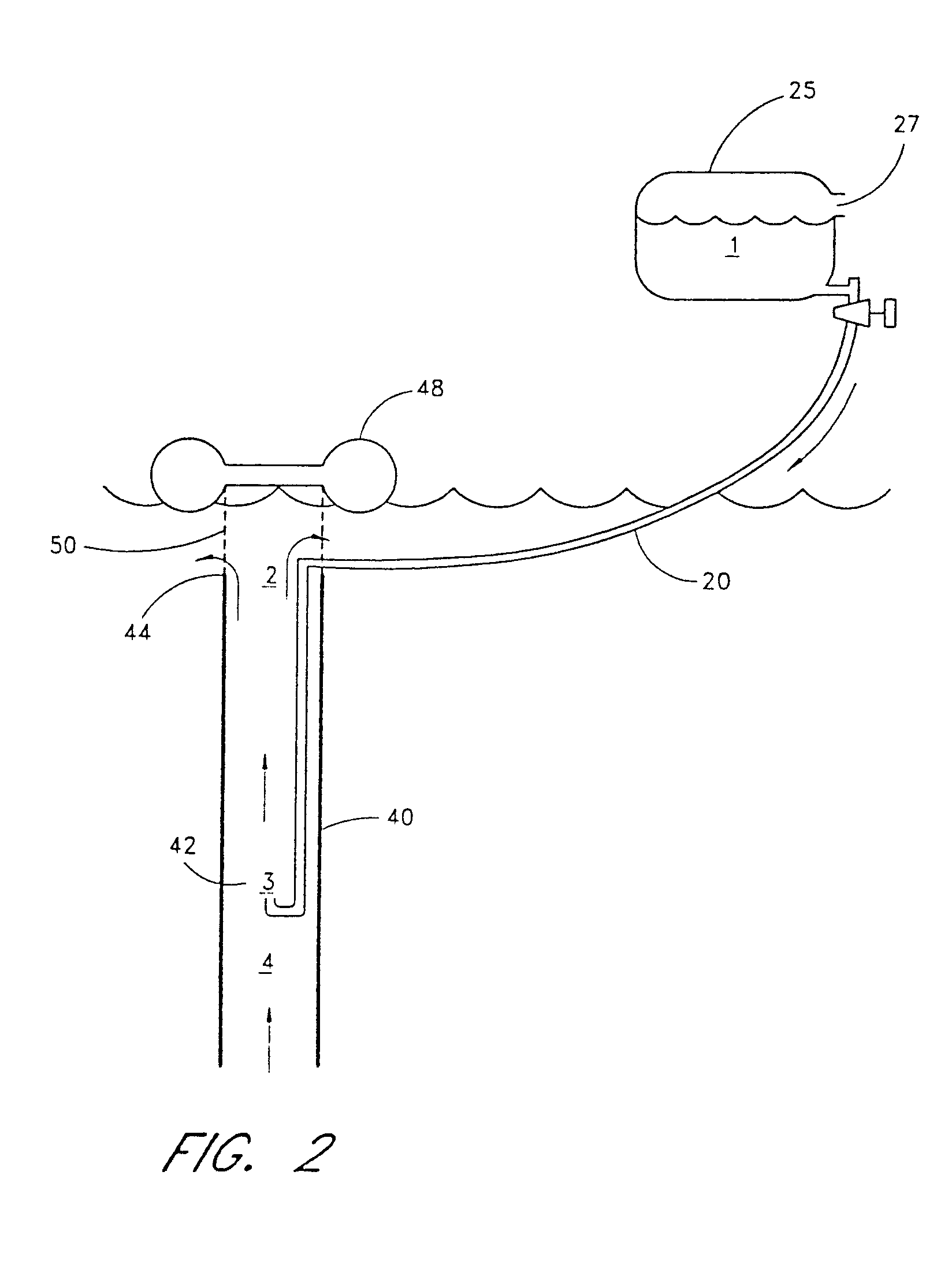
[0141]The apparatus shown in FIG. 2 was used to measure observed flow rates in the up tube 40 with different fresh water flow rates introduced into the down tube 20. Table 1 is a compilation of the results for flow rates at various points in the up tube 40 with two different flow rates of fresh water in the down tube 20. The flow rate at Point 1, the flow rate of fresh water from the reservoir, and the salinity at Point 2 at the outlet end 44 of the up tube 40 were measured parameters. The flow rate at Point 3, the outlet end 24 of the down tube 20, was the same as the flow rate at Point 1. The remaining flow rates were calculated using the equations discussed above.

[0142]

TABLE 1Flow Rates at Various Locations in the Up TubeHeightof ReservoirSalinity at PointFlow (10−4 m3 / sec)(meters)2 (ppt)Point 1Point 2Point 3Point 40.23341.345.51.344.20.55342.484.02.481.6

[0143]The results indicate that the flow rate of the mixed salt-water / fresh-water solution at Point 2 at the outlet end 44 of t...

example 2

Flow Rates Through the Up Tube with Salt Water vs. Fresh Water Introduced into the Down Tube

[0145]For this experiment, a 6″ turbine roof vent was attached to the outlet end 44 of the up tube 40. One of the vanes was painted to allow for the counting of rotations. The reservoir was filled with fresh water having a salinity of 300 ppm in one experiment and with salt water having a salinity of 36,000 ppm in a second experiment. The reservoir was placed at a height of 0.55 meters above the water level of the salt water in the pool. The fresh water was then allowed to flow through the down tube 20, and the rate at which the turbine rotated was determined. Then, salt water from the salt water pool was allowed to flow through the down tube 20, and the rate at which the turbine rotated was again determined. The results are shown in Table 2 below.

[0146]

TABLE 2Turbine Speed with Fresh Water vs. Salt Water in Down TubeDown Tube Water FlowTurbine Speed(10−4 m3 / sec)(rpm)Fresh Water (0.3 ppt)2.45...

example 3

[0154]A series of experiments were carried out using the experimental design described above and as illustrated in FIG. 2, but with down tubes 20 having different diameters. With each down tube 20, the flow rates of the fresh water in the down tube 20 were varied to determine the effect of different fresh water flow rates on available power. The salinity at the outlet end 44 of the up tube 40 was measured, and the water flow rates were calculated from the salinity as before. The water flow rates were used to calculate the available power at Point 2, the outlet end 44 of the up tube 40. The available power was then normalized by dividing the available power by the fresh water flow rate in the down tube 20. The results are shown in Table 4 below.

[0155]

TABLE 4Normalized Power Production vs. Diameter of Up Tube and Fresh Water Flow RatesRatio of Up TubePower / FreshSalinity atFlow (× 0.0001 m3)Down TubeArea to DownWater FlowPoint 2 (ppt)Point 1Point 4Point 2Area (m2)Tube Area(Watts / m3)31....


PUM


Abstract

A mixing apparatus for mixing relatively low salinity fluid with relatively high salinity fluid comprisesa housing having an upper end and a lower end, a fluid inlet at or near the lower end, and a fluid outlet at or near the upper end, wherein the relatively high salinity fluid in use enters the housing through the fluid inlet and is discharged from the housing through the fluid outlet. A feed tube is provided and has a first end connectable to a source of relatively low salinity fluid and second end for introducing relatively low salinity fluid to the housing to mix the relatively high salinity fluid with the relatively low salinity fluid to form a fluid mixture. At least one power generator is associated with the housing, and is driven by the mixing of the relatively high salinity fluid with the relatively low salinity fluid.

Description

CROSS REFERENCE TO RELATED APPLICATIONS[0001]This application is a continuation-in-part of U.S. patent application Ser. No. 11 / 096,981 filed Mar. 31, 2005, which is a continuation-in-part application of U.S. patent application Ser. No. 10 / 777,458 filed Feb. 12, 2004 now U.S. Pat No. 7,132,759, which is a continuation-in-part application of U.S. patent application Ser. No. 10 / 357,007 filed Feb. 3, 2003 and also a continuation-in-part of U.S. patent application Ser. No. 10 / 404,488 filed Mar. 31, 2003 now abandoned. U.S. patent application Ser. No. 10 / 357,007 is continuation-in-part of, and U.S. patent application Ser. No. 10 / 404,488 is a continuation of, U.S. patent application Ser. No. 09 / 952,564 filed Sep. 12, 2001, now U.S. Pat. No. 6,559,554, which is a continuation-in-part of U.S. patent application Ser. No. 09 / 415,170 filed Oct. 8, 1999, now U.S. Pat. No. 6,313,545. U.S. patent application Ser. No. 09 / 415,170 itself claims the benefit of Provisional Patent Applications Nos. 60 / 1...

Claims


Application Information

Patent Timeline
Patent Type & Authority Patents(United States)
IPC IPC(8): F03D9/00
CPCF03B13/00F03G7/04Y02E10/36Y02E10/30
Inventor ALSTOT, GARYJONES, ANTHONY T.FINLEY, WARRENPSCHEIDT, EDWARDDOLBEAR, GEOFFREY E.
Owner WADER
Why Eureka
Try Eureka