[0005]Indeed, for industrial applications like
quality control or inspection tasks it is less important to find elastic or articulated objects, but to find objects that consist of several parts that show arbitrary mutual movement, i.e., variations in distance, orientation, and scale. These variations potentially occur whenever a process is split into several single procedures that are—by intention or not—insufficiently “aligned” to each other, e.g., when applying a
tampon print using several stamps or when equipping a circuit board with transistors or
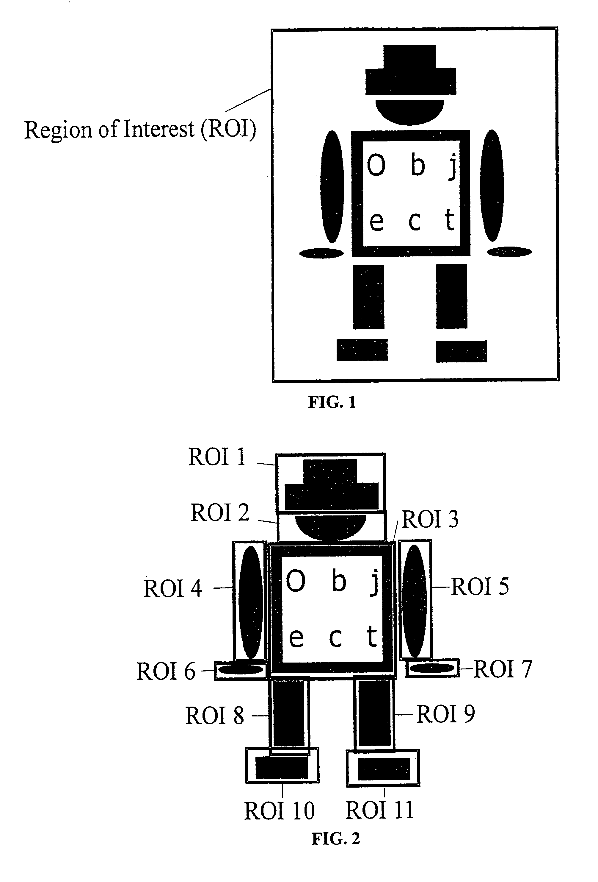
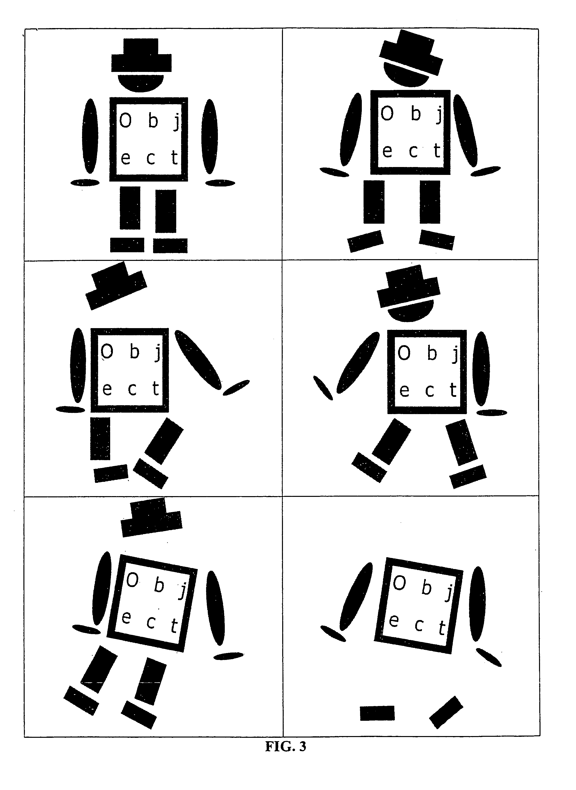
soldering points. In FIG. 1 an example object is shown. FIG. 3 illustrates the mutual movements (variations) of the object parts. Clearly, when taking such kind of objects as rigid it may not be found by conventional object recognition approaches. However, when trying to find the individual parts separately the search becomes computationally expensive since each part must be searched for in the entire image and the relations between the parts are not taken into account. This problem can hardly be solved taking articulated objects into account since there is no true justification for hinges, but the mutual variations can be more general. Because the object may, for example, consist of several rigid parts, obviously, also elastic objects cannot model these movements. One possible solution is to generate several models, where each model represents one configuration of the model parts and to match all of these models to the image. However, for large variations, this is very inefficient and not practical for real-time computation. In U.S. Pat. No. 6,324,299 (R1) a method of locating objects is described where the object has a plurality of portions. In a first step the coarse
pose of the object is determined and in a subsequent step the fine poses of the object portions are calculated. Therefore, the variations of the portions must be small enough to find the coarse pose of the object, in contrast to the present invention, where the variations are explicitly modeled and may be of arbitrary form and of arbitrary size. Additionally, in U.S. Pat. No. 6,324,299 the variations are not automatically learned in a
training phase as it is done in the present invention. U.S. Pat. No. 6,411,734 (R2) extends the method presented in U.S. Pat. No. 6,324,299 by checking the found object portions whether they fail to satisfy user-specified requirements like limits on the poses of the object portions. The
advantage of the present invention is that this check can be omitted since the object parts are only searched over the range of valid poses and therefore, only valid instances are returned.
[0006]This invention provides a method for automatically learning a hierarchical object recognition model that can be used to recognize objects in an image, where the objects consist of several parts that are allowed to move with respect to each other in an arbitrary way. The invention automatically decomposes the object into its parts using several example images in which the mutual movements (variations) of the object parts are shown and analyzes the variations. In a preferred embodiment, the single object parts are assumed to be rigid, thus showing no deformations. In a further preferred embodiment only rigid transformations (translation and rotation) are taken into account. Thus, the objects can be found if they are at arbitrary position and orientation in the image. Additional pose parameters, e.g., scale, can be taken into account in a straightforward manner.
[0007]The mutual variations of the object parts are analyzed and used to build a hierarchical model that contains representations of all rigid object parts and a
hierarchical search strategy, where the parts are searched relatively to each other taking the relations between the parts into account.
[0008]This generation of the hierarchical model will be called offline phase and must be executed only once and therefore is not time-critical. But in the
time critical online phase, in which the object is searched in an image, the hierarchical model facilitates a very efficient search.
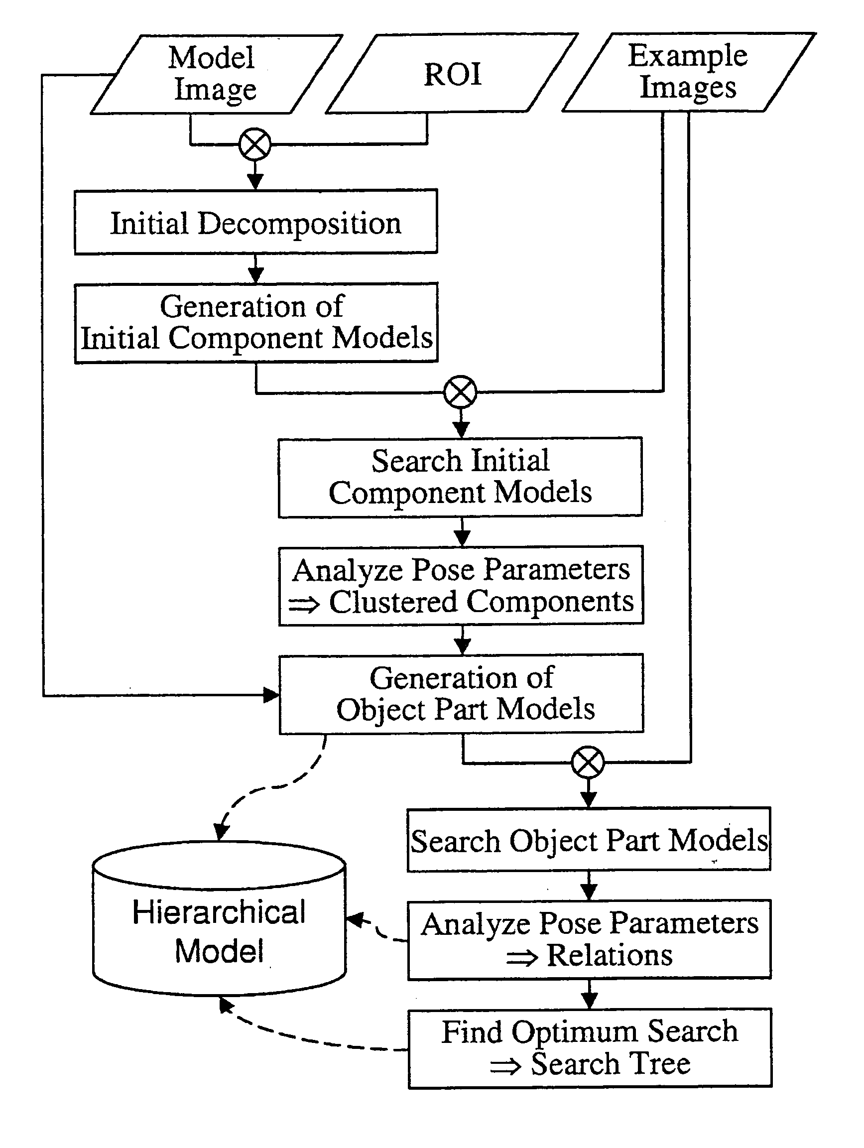
[0009]The single steps of the hierarchical model computation are shown in the
flowchart of FIG. 4. The only input data of the proposed
algorithm are a
sample image of the object (
model image), in which the object is defined by the user, e.g., using a
region of interest (ROI), and some additional example images that, at least qualitatively, describe the mutual movements of the single object parts.
[0010]The first step is to decompose the object, which is defined by the ROI within the
model image, into small initial components. Note that these components need not coincide with the real object parts. For instance, if the connected components of the image edges are used as criterion for
decomposition the following components would result from the example of FIG. 1: 1 hat, 1 face, 2 arms, 2 hands, 2 legs, 2 feet, the outer rectangle of the upper body, the inner rectangle of the upper body and at least 1 component for each letter printed on the upper body. For each initial component a representation is calculated that can be used to search the initial component in the example images. This representation will be called initial component model and can be built using an arbitrary recognition method that is able to find objects under at least
rigid transformation (translation and rotation). In a preferred embodiment of the invention a recognition method that is based on the image edges is used. Additionally, if industrial demands are to be fulfilled the
similarity measure described in R21 or in “
System and method for object recognition”, European
patent application 00120269.6, (R22) or the modified
Hough transform (R24) should be preferred.

