Integrated sensing system

a sensing system and integrated technology, applied in the direction of navigation instruments, axle suspensions, process and machine control, etc., can solve the problems of large rolling motion towards the outside, unattainable navigation solutions within the ins, and increase computation errors, so as to improve the accuracy of current vehicle dynamics, reduce unnecessary fuel consumption, and improve the accuracy of predicted road conditions

Active Publication Date: 2007-07-03
FORD GLOBAL TECH LLC
View PDF327 Cites 79 Cited by
  • Summary
  • Abstract
  • Description
  • Claims
  • Application Information

AI Technical Summary

Benefits of technology

[0017]Thus, the present system may be incorporated in but not limited to a rollover stability control system (RSC), a yaw stability control system, an ABS / TCS control system and a power-train control system for fuel economy purpose. One advantage of the invention is that the sensor cluster in tandem with the integrated controller generates accurate vehicle attitude and velocity signals. More specific example is the vehicle longitudinal velocity. During braking or throttle conditions, the wheel speed signal alone would not be able to generate accurate vehicle reference speed (longitudinal velocity) which is used in wheel slip control for achieving RSC / TCS / ABS functions. When the wheels of one side of the vehicle are up in the air (due to large roll trending of the vehicle), those wheel speed information are no longer the valid indications of the vehicle speed. In off-road driving, more than one wheel could behave independently of the vehicle speed.
[0018]Another advantage is the substantially improved accuracy of current vehicle dynamics and predicted vehicle dynamics as used in but not limited to rollover stability control systems, yaw stability control systems, ABS / TCS control systems, power-train control systems.
[0019]A further advantage is the substantially improved accuracy of the predicted road conditions on which the vehicle is driven. For example, the accurate identification of the road inclination could help the throttle control system to cut unnecessary fuel consumption during down hill driving; the accurate identification of the road surface friction condition could help RSC and yaw stability control.
[0020]Still a further advantage is the ability to identify the vehicle parameter changes. For example, the loading or mass variation of the vehicle could be identified so that appropriate level of control actions could be adjusted in proportional to the vehicle loadings.
[0021]Another advantage is the ability to detect the sensor misalignment errors and sensor plausibility check. The sensor misalignment errors have two portions (i) the sensor mounting errors; (ii) the uneven loading conditions generating misalignment between the loading vehicle and the unloading vehicle. Such an identification of the sensor misalignment errors could substantially improve the accuracy of the predicted vehicle operation states.
[0022]Another advantage is the ability to substantially improve the performance of the four wheel drive vehicle due to the accurate identification of the force and torque applied to the wheels. Therefore, both the command drive torque and the resultant torque on the wheel end can be accurately identified so as to increase the efficiency of the torque-on-demand strategy.

Problems solved by technology

For example, excessive steering of a vehicle may lead to excessive yaw and lateral motion, which could cause large rolling motion towards the outside of a turn.
Although INS systems are sufficient to generate a navigation solution, over time the computation based on IMU sensor signals drifts, and the errors associated with the computation increases.
Sometimes these errors increase such that a navigation solution is unattainable within the INS.
Current automotive vehicle systems experience a similar signal drift problem in vehicle attitude determination.
Although the drift is not as severe as in aerospace vehicles, it generates errors within the vehicle control system such that the vehicle control system engages improper actions.

Method used


Image

  • Integrated sensing system
  • Integrated sensing system
  • Integrated sensing system

Examples


Embodiment Construction

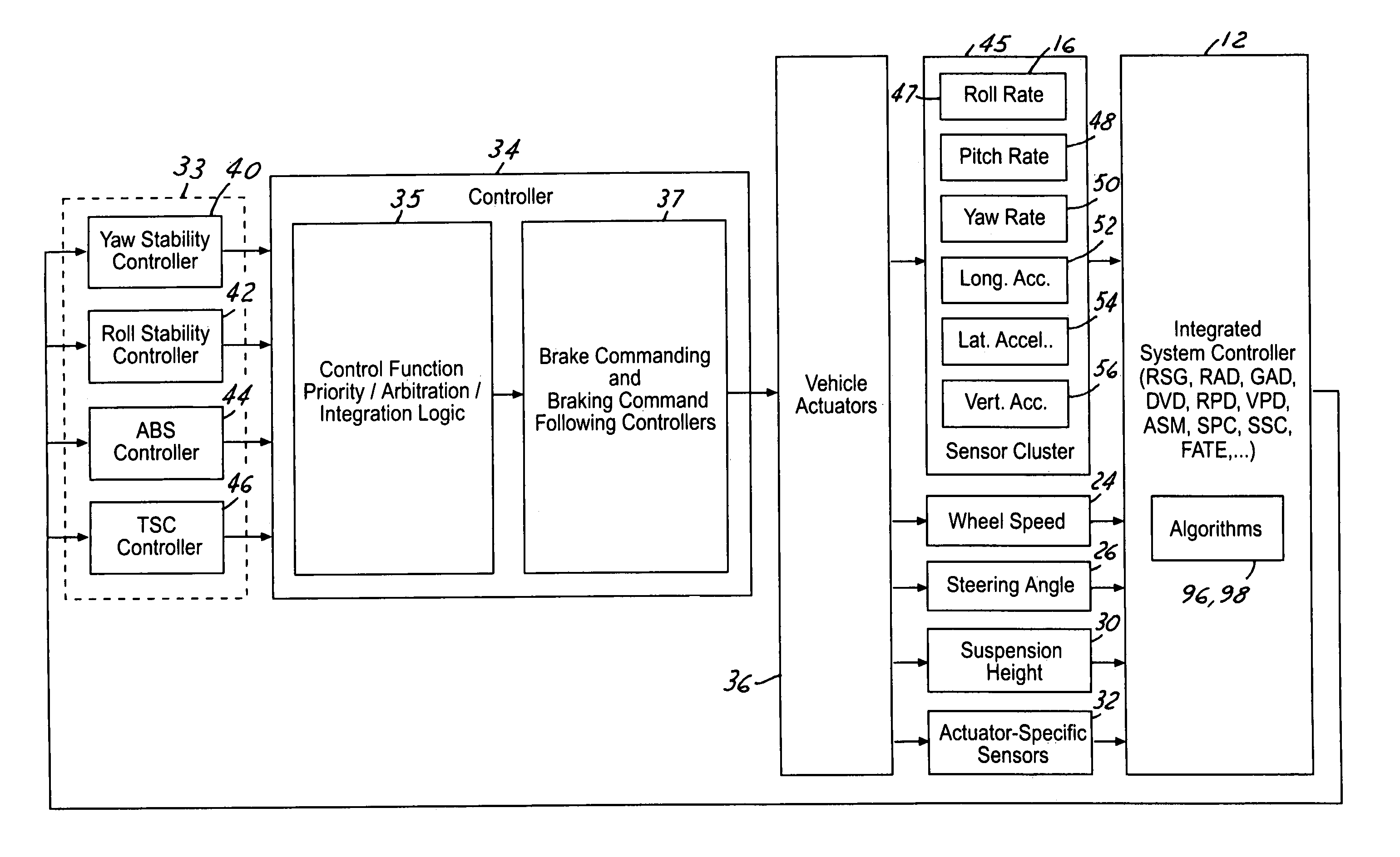
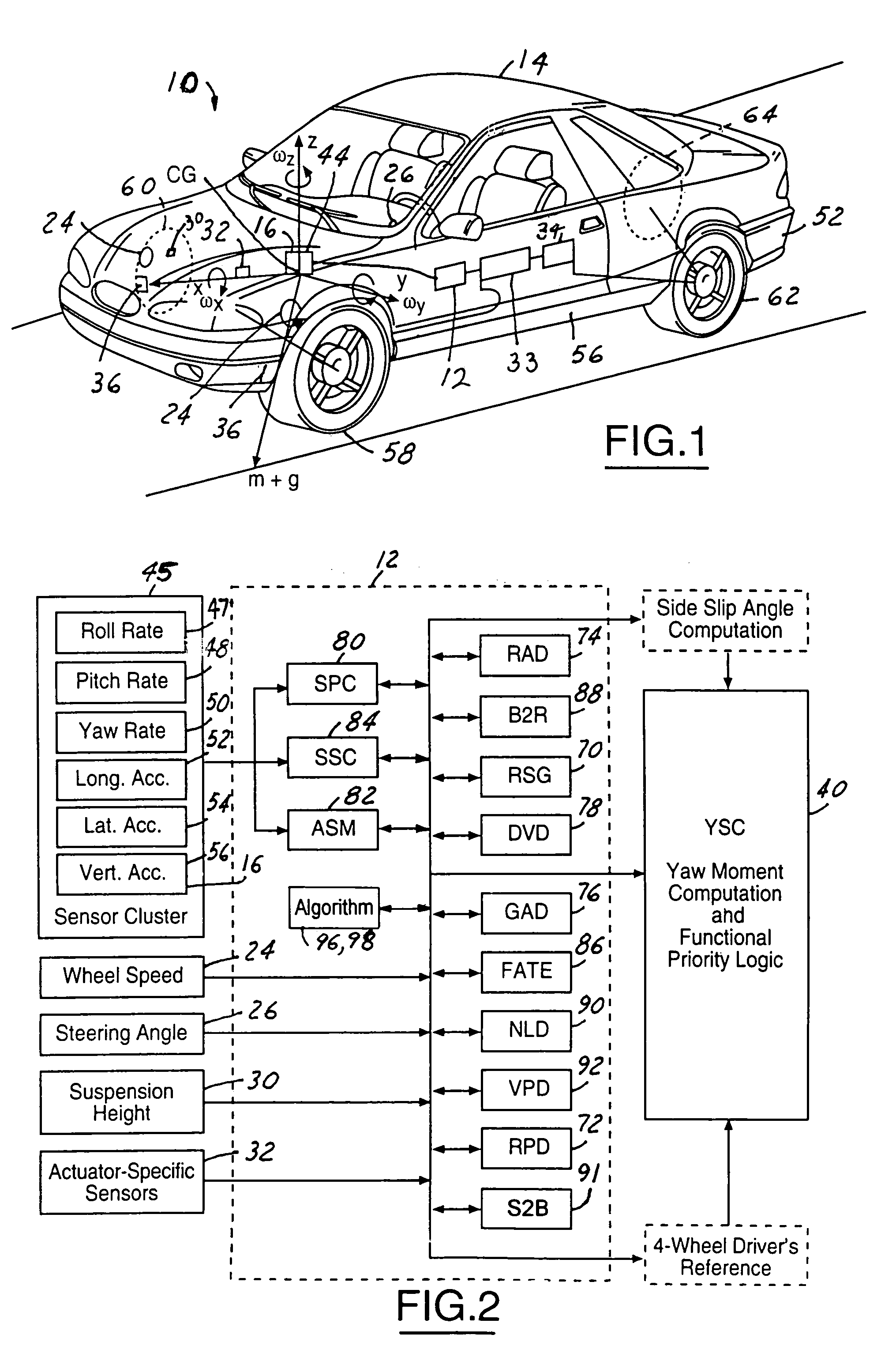
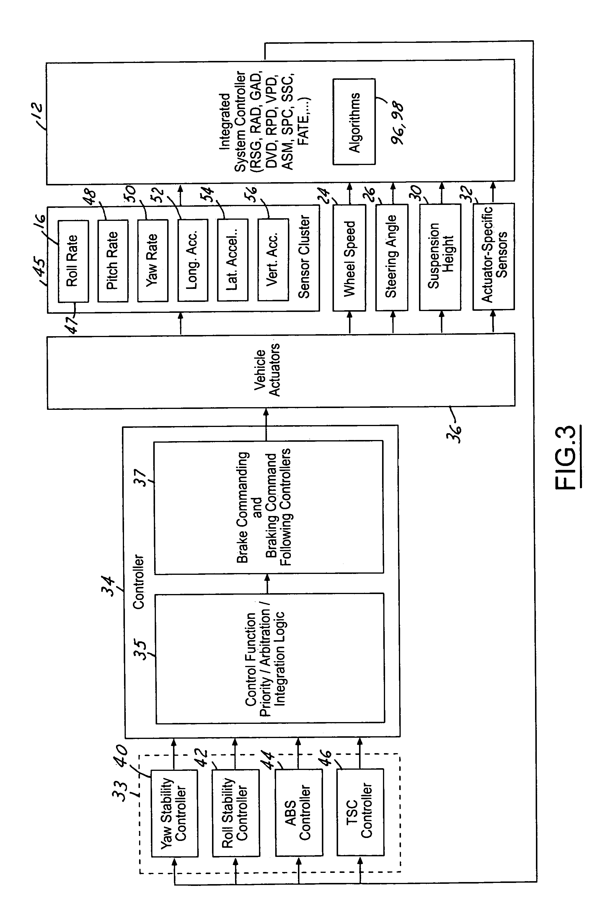
[0032]In the following Figures the same reference numerals will be used to identify the same components. The present invention is preferably used in conjunction with vehicle control systems, which include, but are not limited to a yaw stability control system, a roll stability control system, an integrated vehicle dynamics control system, or a total vehicle control system for achieving fuel economy and safety and other vehicle level performances.

[0033]The integrated system controller or integrated sensing system controller (ISS) in the present invention estimates and predicts the vehicle operation states including vehicle global and relative attitudes, vehicle directional velocities, forces and torques applied to a vehicle, etc.; generates a sensor plausibility check; monitors the abnormal conditions of the moving vehicle; and corrects the sensor mounting errors of the sensors. The information generated from the integrated system controller is used to initiate control commands for v...


PUM


Abstract

A vehicle control system includes a housed sensor cluster generating a plurality of signals. An integrated controller includes a sensor signal compensation unit and a kinematics unit, wherein the sensor signal compensation unit receives at least one of the plurality of signals and compensates for an offset within the signal and generates a compensated signal as a function thereof. The integrated controller further generates a kinematics signal including a sensor frame with respect to an intermediate axis system as a function of the compensated signal and generates a vehicle frame signal as a function of the kinematics signal. A dynamic system controller receives the vehicle frame signal and generates a dynamic control signal in response thereto. A safety device controller receives the dynamic control signal and further generates a safety device signal in response thereto.

Description

CROSS-REFERENCE TO RELATED APPLICATIONS[0001]The present invention is related to provisional application 60 / 449,940 entitled “Integrated Sensing System for an Automotive System,” filed on Feb. 26, 2003 and incorporated by reference herein.TECHNICAL FIELD[0002]The present invention relates generally to a vehicle sensing system and, more specifically, to a system for controlling an automotive vehicle in response to sensed dynamic behavior from the sensing system.BACKGROUND[0003]Various automotive vehicles have recently begun including vehicle dynamic control systems. Such vehicle dynamic control systems include yaw stability control systems, roll stability control systems, integrated vehicle dynamic control systems, etc. The ongoing goal of vehicle controls is to achieve a coordinated, system of vehicle performance for ride, handling, safety and fuel economy.[0004]With current advances in mechatronics, vehicle controls have increased opportunities for achieving performances, which wer...

Claims


Application Information

Patent Timeline
Patent Type & Authority Patents(United States)
IPC IPC(8): G06F19/00G01C21/26B60G17/015B60G17/018B60G17/0185B60G17/019B60G17/0195G06F7/70G06G7/00
CPCB60G17/018B60G17/0185B60G17/019B60G17/0195B60G2400/0521B60G2400/0522B60G2400/0523B60G2400/102B60G2400/104B60G2400/106B60G2600/08B60G2800/70
Inventor LU, JIANBOBROWN, TODD ALLENXU, LIMEYERS, JOSEPH CARR
Owner FORD GLOBAL TECH LLC
Why Eureka
Try Eureka