
Crawler, crawler pin, crawler bush, and crawler manufacturing method

a manufacturing method and technology for crawlers, applied in the direction of ring springs, vehicle cleaning, driving chains, etc., can solve the problems of crawler bush breaking more frequently, seizure cannot be avoided, etc., to improve the long-term holdability of the above grease or lubricating oil, and the lifetime of the crawler is easily shortened

Inactive Publication Date: 2007-07-10
KOMATSU LTD
View PDF30 Cites 13 Cited by
  • Summary
  • Abstract
  • Description
  • Claims
  • Application Information

AI Technical Summary

Benefits of technology

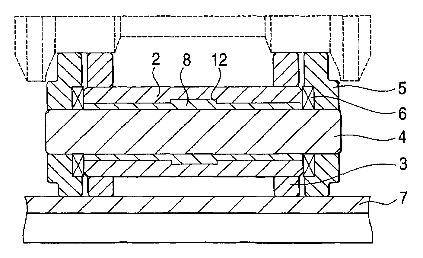
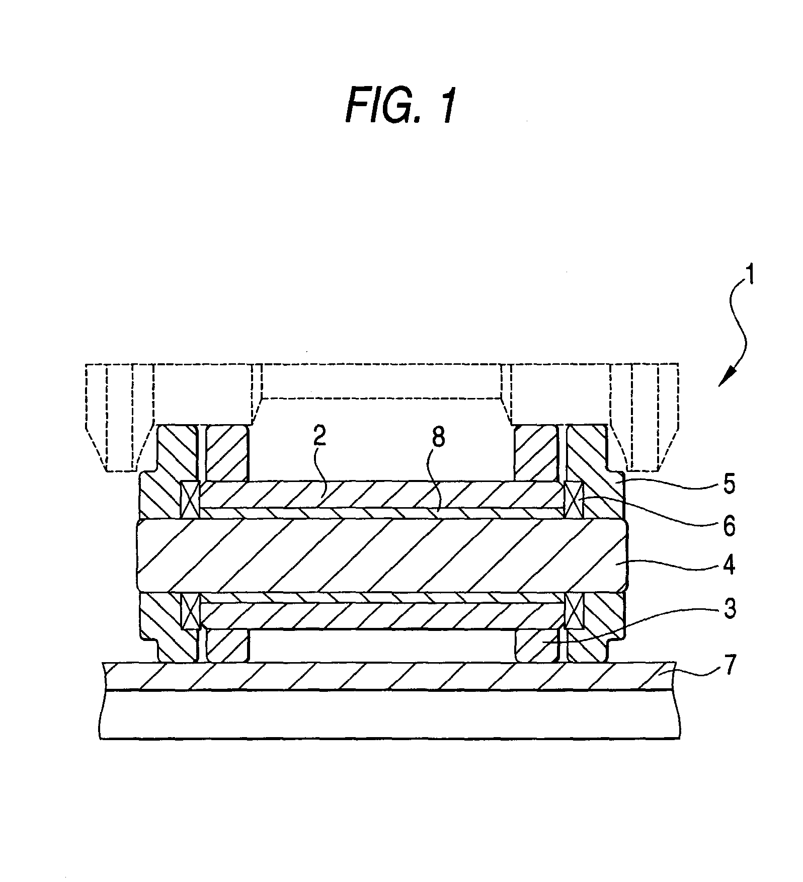
The invention provides a solution to problems such as unbalanced load, seizure, and hammering noises in a crawler by introducing a metallic sliding member with a structure capable of holding lubricating oil and / or grease between the crawler bush and the crawler pin. The metallic sliding member has a clearance between the crawler bush and the crawler pin, which can be narrowed to retain higher crawler strength and prevent seizure. The metallic sliding member also helps to absorb the hammering noises and provides a quieter and more stable crawler. Additionally, the invention provides a solution to the problem of wear on the crawler bush by using a rotary bush to mesh with the drive sprocket. The metallic sliding member can be made of a metallic sintered sliding material with pores impregnated with lubricating oil to enhance lubrication and sound absorption.

Problems solved by technology

When the aforementioned unbalanced load increases, there arise the problem that the occurrence of the seizure cannot be avoided, and the problem that the crawler bush breaks the more frequently for the larger clearance.

Method used


Image

  • Crawler, crawler pin, crawler bush, and crawler manufacturing method
  • Crawler, crawler pin, crawler bush, and crawler manufacturing method
  • Crawler, crawler pin, crawler bush, and crawler manufacturing method

Examples


example 1

Relations between Crawler Bush—Pin Clearance and Breaking Strength

[0104]In this Example, by using a crawler bush having an external diameter of 59.4 mm, an internal diameter of 38.6 mm and a length of 138.5 mm and a crawler pin and by using an impact fatigue testing apparatus shown in FIG. 10, impact fatigue tests were done to examine the influences the clearance between the crawler bush and the crawler pin upon the crawler bush breaking strength and to examine the inserting actions of the metallic sliding member upon the crawler bush breaking strength. Here, the crawler bush was quenched to have a hardened depth of about 3 mm at the HRC45 position by induction-quenching a material SCr440 on both the outer circumference and the inner circumference and was tempered at 180° C. for 3 hrs. On the other hand, the crawler pin was prepared to have a hardened depth of about 4 mm by water-quenching an S45BC material from 850° C. and was tempered at 180° C. for 3 hrs.

[0105]Moreover, the impac...

example 2

Manufacture and Sliding Test Results of CuAl Type Sintered Sheet

[0110]By using Al powder, Sn powder, TiH powder, Si powder, Mn powder, Ni powder, phosphor iron powder and electrolytic cathode copper powder (e.g., CE15 of Fukuda Kinzoku) of 300 meshes or less, mixed powders, as enumerated in Table 1, were molded under a molding pressure of 4 tons / cm2 by using a tensile test piece mold of JIS, as shown in FIG. 13. These test pieces were sintered at a degree of vacuum of 0.01 torrs, at 850, 900 and 960° C., for 1 hr by using a vacuum sintering furnace. After this, the test pieces were rolled within an uncracked range and sintered again at the same temperature for 1 hr. The resultant test pieces (of 2S1R material) were measured on their hardness. Moreover, these materials were measured by the constant rate friction wear testing method on the seizure limit values (i.e., PV values) and the wear losses (ΔW, mm) at that time from the bearing pressure, at which the friction coefficient rises...


PUM


Abstract

A crawler having a crawler pin and a crawler bush having lubrication between the crawler pin and the crawler bush without lowering the strength of the crawler at the running time, thereby to prevent the creak or seizure, as might otherwise be caused at the running time. A metallic sliding member having an excellent wear resistance can be arranged in the clearance between the crawler bush and the crawler pin. The metallic sliding member can be capable of holding lubricating oil and / or a lubricant. In addition, the clearance between the core bush and the crawler pin can be narrowed, so that the resulting structure retains the imbalance load on both the crawler bush and the crawler pin.

Description

BACKGROUND OF THE INVENTION[0001]1. Field of the Invention[0002]The present invention relates to a crawler, a crawler pin, a crawler bush or a crawler manufacturing method, which is to be used in a construction or civil engineering machine such as a excavator or a bulldozer.[0003]2. Related Art[0004]As shown in FIG. 17A, a crawler 50 of a construction machine is generally constructed to include: a crawler shoe 51; a pair of crawler links 52 and 53 fixed on the crawler shoe 51 by means of bolts; a crawler bush 54 press-fitted / fitted in the holes formed in the crawler links 52 and 53; and a crawler pin 55 inserted into the crawler bush 54 and press-fitted / fitted in the holes of the crawler links 52 and 53. As the toothed sprocket of a drive sprocket meshes with the crawler bush 54 press-fitted between the crawler links 52 and 53, the crawler 50 turns to run the construction machine. Between the end portions of the crawler bush 54 and the crawler pin 55, as shown in FIG. 17B, there are...

Claims


Application Information

Patent Timeline
Patent Type & Authority Patents(United States)
IPC IPC(8): B62D55/205E02F9/02B62D55/21B62D55/215B62D55/253
CPCB62D55/211B62D55/215
Inventor TAKAYAMA, TAKEMORI
Owner KOMATSU LTD
Learn More