Passive vibration isolation of implanted microphone

a passive vibration and microphone technology, applied in the field of implanted microphones, can solve the problems of unsatisfactory vibration (e.g., non-sound vibration) originating within the user's skull and/or tissue, can not be detected and amplified by the microphone to an undesirable degree, and create such vibration, so as to reduce the amount of non-ambient vibration energy and improve the attenuation properties of the compliant base member

Inactive Publication Date: 2007-07-10
COCHLEAR LIMITED
View PDF3 Cites 11 Cited by
  • Summary
  • Abstract
  • Description
  • Claims
  • Application Information

AI Technical Summary

Benefits of technology

[0009]This natural frequency may be set to a value advantageous in isolating the microphone against sources of non-ambient vibration. Preferably, the compliant member is selected so that the suspended system has a natural, or resonant, frequency that is less than the lowest frequency of non-ambient vibration to be attenuated (e.g., about 100 Hz). It is more desirable that the natural frequency be less than ½ the lowest frequency in the frequency range to be attenuated. It is still more desirable that the natural frequency be less than ⅕ the lowest frequency in the frequency range to be attenuated. For example, when the natural frequency of the suspended system is ⅕ that of the lowest frequency to be attenuated, transmission of that frequency will be reduced to 1 / 24th its original value. In this way, the present invention reduces the system's sensitivity to non-ambient vibrations, while preserving its sensitivity to ambient vibrations (e.g., desired sound vibrations).
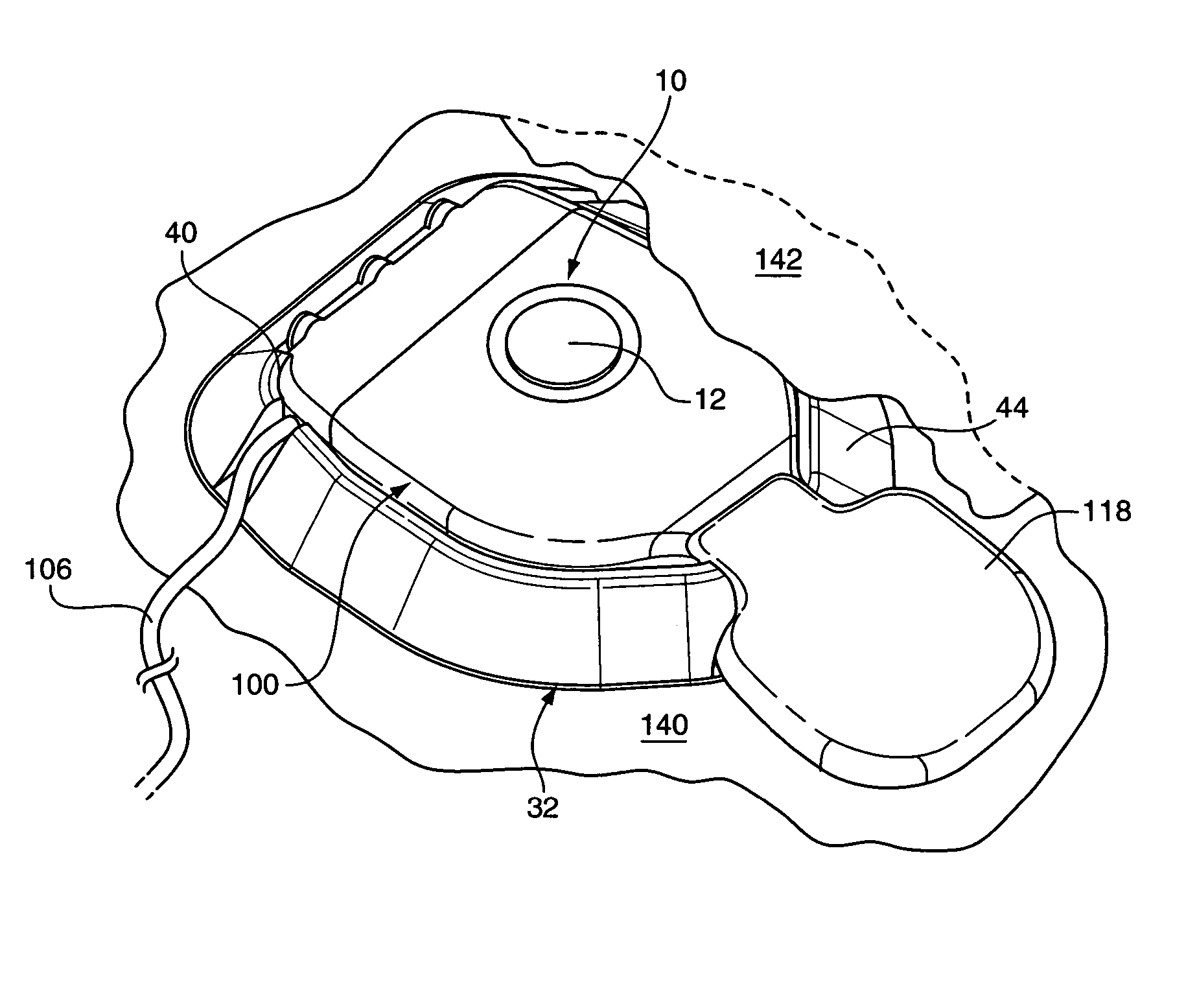
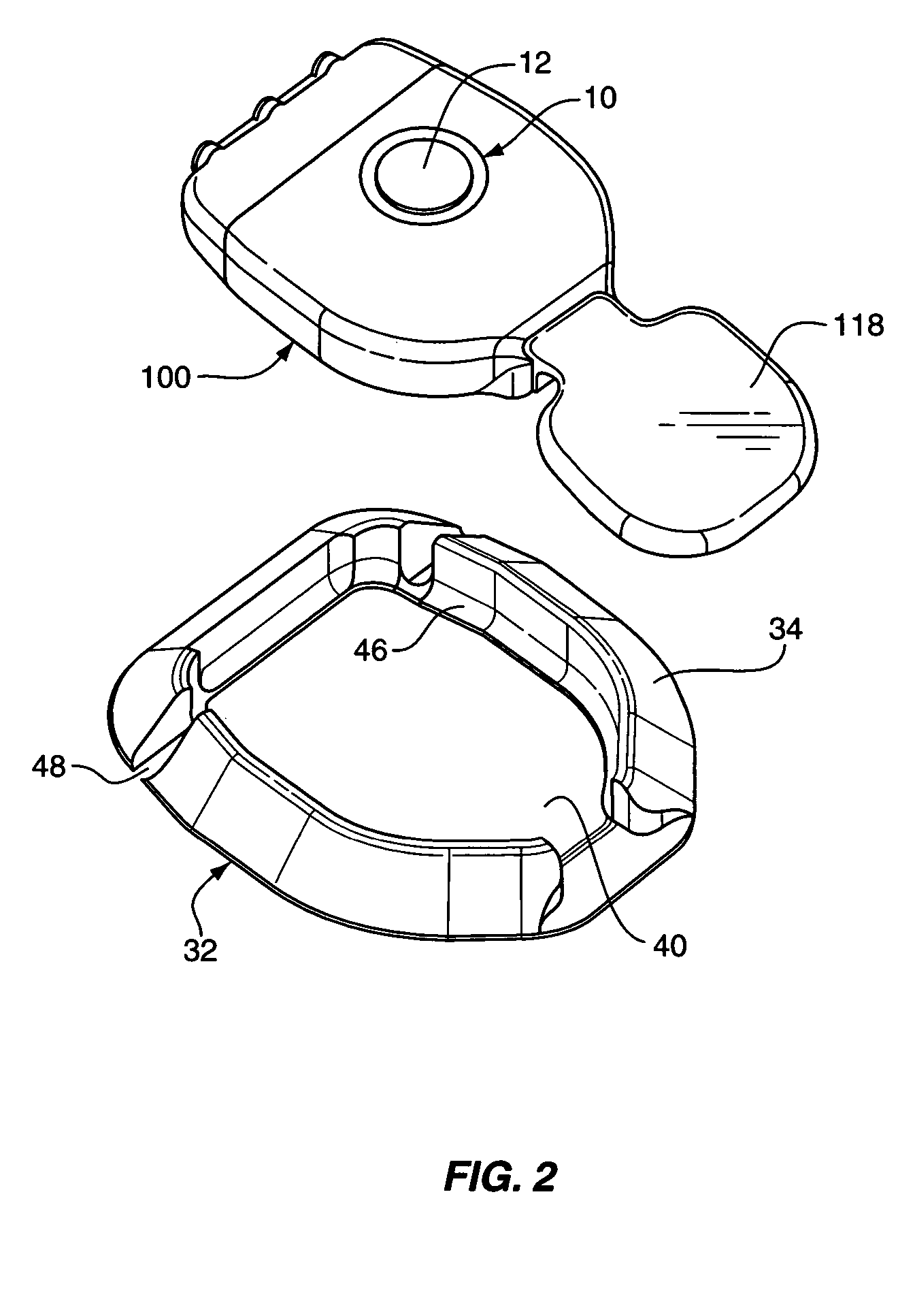
[0013]In one aspect, a system for isolating an implantable hearing aid microphone from non-ambient vibrations (e.g., non-desired vibrations) is provided. The system includes an implant housing, a microphone and a first compliant member for disposition between a source of non-ambient vibration and the implant housing and / or the microphone. The microphone may be supportably interconnected relative to the implant housing such that a diaphragm of the microphone is located to receive ambient sound vibrations. Accordingly, the first compliant member may be disposed to at least partially isolate the microphone from non-ambient vibrations, which may facilitate the receipt of incident ambient sound-vibrations.
[0016]When the compliant base member is substantially cup-shaped, a peripheral rim of the compliant base member may be tapered, or beveled, from an outer edge of a bone-facing side to an edge of a receiving-recess on an opposite side (i.e., the cup-shaped side). In this regard, the compliant base member may provide a distributed surface for the support of skin overlying the implant, reducing discomfort and the potential or reduced circulation.
[0018]In order to improve the attenuation properties of the compliant base member, one or more additives may be added to the material forming the base member. For instance, dispersion of solid materials, such as titanium flakes, throughout the matrix of the base member (e.g., during base formation) may allow the base member to reflect / redirect a portion of received vibration energy and thereby reduce the amount of non-ambient vibration energy that is received by the implant housing. Alternatively or in addition, compressible gases may be added to the matrix of the compliant base member. In this regard, bubbles may be formed within the matrix, or, gas filled glass beads may be mixed therein. In either case, such voids may be operative to reflect non-ambient vibrations passing through the base member and thereby dampen / attenuate such vibrations.

Problems solved by technology

For a wearer of such a hearing instrument (e.g., middle ear transducer or cochlear implant stimulation systems), undesirable vibration (e.g., non-sound vibration) originating within the user's skull and / or tissue may be detected and amplified by the microphone to an undesirable degree.
For instance, a middle ear transducer used with a hearing instrument may create such vibration.
In this case, detection and amplification of the vibration can lead to objectionable feedback.
In both cases, undesired vibrations are transmitted through the user's skull or tissue to the site of the implanted microphone where a component of these undesired vibrations may be received by a microphone diaphragm and where the skin and tissue covering such a microphone diaphragm may undesirably increase the overall vibration sensitivity of the system.

Method used


Image

  • Passive vibration isolation of implanted microphone
  • Passive vibration isolation of implanted microphone
  • Passive vibration isolation of implanted microphone

Examples


Embodiment Construction

[0038]Reference will now be made to the accompanying drawings, which at least assist in illustrating the various pertinent features of the present invention. In this regard, the following description of a hearing instrument is presented for purposes of illustration and description. Furthermore, the description is not intended to limit the invention to the form disclosed herein. Consequently, variations and modifications commensurate with the following teachings, and skill and knowledge of the relevant art, are within the scope of the present invention. The embodiments described herein are further intended to explain the best modes known of practicing the invention and to enable others skilled in the art to utilize the invention in such, or other embodiments and with various modifications required by the particular application(s) or use(s) of the present invention.

Hearing Instrument System:

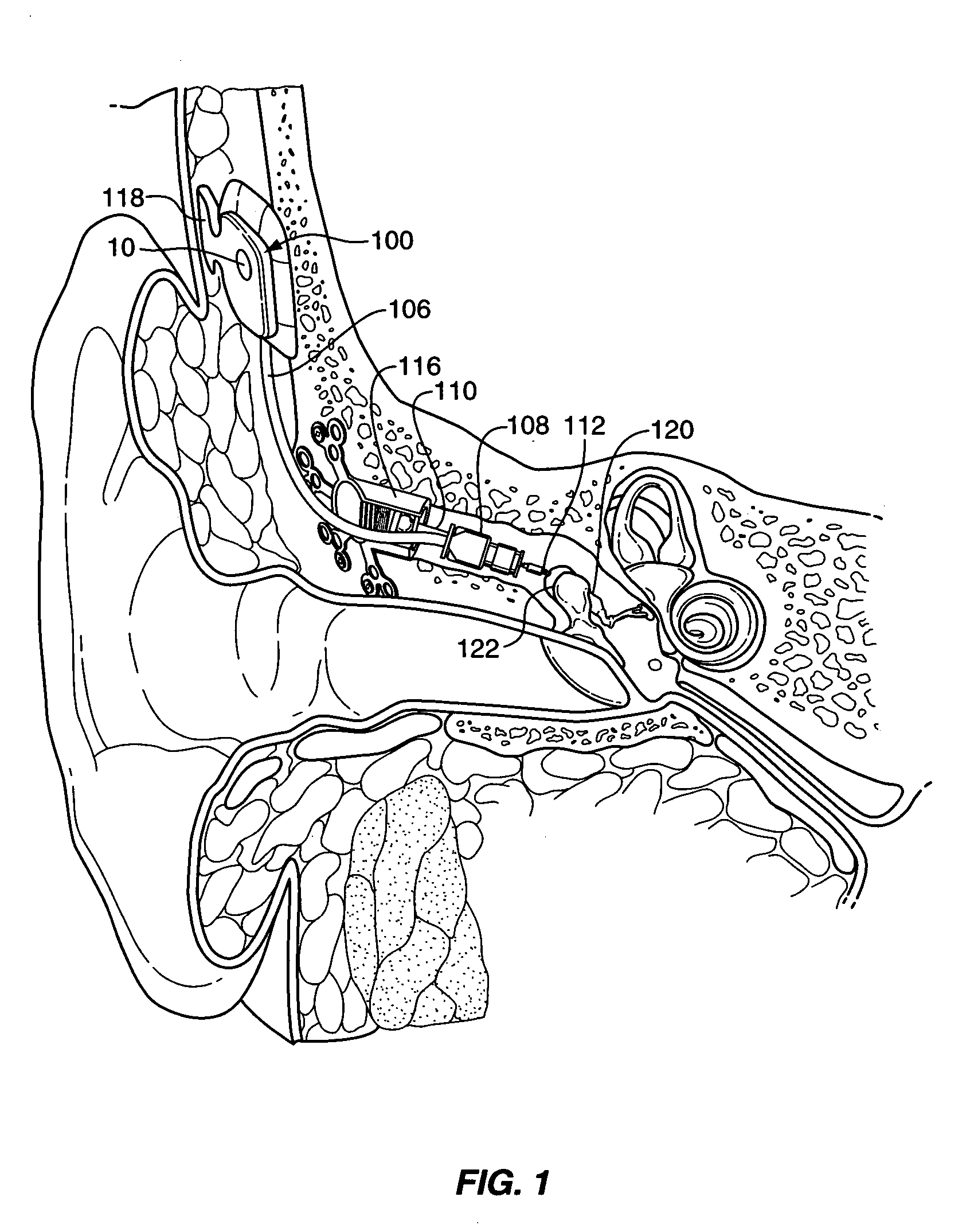
[0039]FIG. 1 illustrates one application of the present invention. As illustrated, the applicat...


PUM


Abstract

A system for reducing the vibration sensitivity of an implantable microphone without an equal or greater reduction in sound sensitivity. The system reduces non-ambient vibrations by placing at least one compliant member into the path of transmission for tissue-borne vibration, but not into the path for ambient sound-induced vibration. More particularly, a compliant member is interposed along the path between a source of non-ambient vibration and an implanted microphone. In one aspect, a compliant base member is disposed between an implanted microphone and an implant wearer's skull. In another aspect, a microphone is compliantly suspended relative to an implant housing using a support membrane. In either aspect, the compliant member (i.e., base member and / or membrane) and the supported member (i.e., housing and / or microphone) define a supported system having a natural or resonant frequency. This natural frequency may be set to a value to advantageously isolate the microphone against transmitted vibration.

Description

CROSS REFERENCE TO RELATED APPLICATIONS[0001]This application claims priority under 35 U.S.C. 119 to U.S. Provisional Application No. 60 / 518,479 entitled: “Passive Vibration Isolation of Implanted Microphone Assembly,” having a filing date of Nov. 7, 2003; and U.S. Provisional Application No. 60 / 518,255 entitled: “Passive Vibration Isolation of Implanted Hearing System Capsule,” having a filing date of Nov. 7, 2003, the contents of which are incorporated herein as if set forth in full.FIELD OF THE INVENTION[0002]The present invention relates to implanted microphones, e.g., as employed in hearing aid systems and, more particularly, to implanted microphones having reduced sensitivity to undesired sources of vibration.BACKGROUND OF THE INVENTION[0003]In the class of hearing aid systems generally referred to as implantable hearing instruments, some or all of various hearing augmentation componentry is positioned subcutaneously on or within a patient's skull, typically at locations proxi...

Claims


Application Information

Patent Timeline
Patent Type & Authority Patents(United States)
IPC IPC(8): H04R25/00H04R
CPCH04R25/604H04R19/016H04R25/606H04R2225/67
Inventor MILLER, III, SCOTT ALLANWALDMANN, BERNDANDREWS, TRAVIS RIANBASINGER, DAVID L.BEDOYA, JOSE' H.EASTER, JAMES ROYKASIC, II, JAMES FRANKMILLER, DOUGLAS
Owner COCHLEAR LIMITED
Why Eureka
Try Eureka