Electric flame control using corona discharge enhancement

a technology of electric field and corona discharge, which is applied in the ignition of turbine/propulsion engine, combustion using lump and pulverulent fuel, combustion types, etc., can solve the problems of not being able to change the burning velocity, electric field becomes less effective, and the use of electric field to significantly impact high-speed turbulent flames has not been demonstrated. , to achieve the effect of reducing nitrogen oxide emissions

Inactive Publication Date: 2007-07-17
SIEMENS ENERGY INC
View PDF14 Cites 95 Cited by
  • Summary
  • Abstract
  • Description
  • Claims
  • Application Information

AI Technical Summary

Benefits of technology

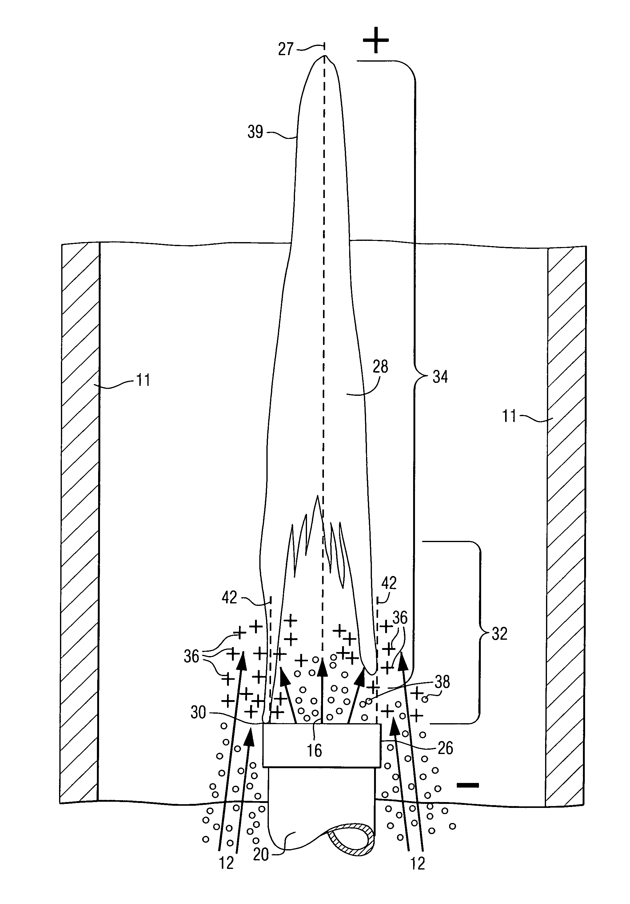
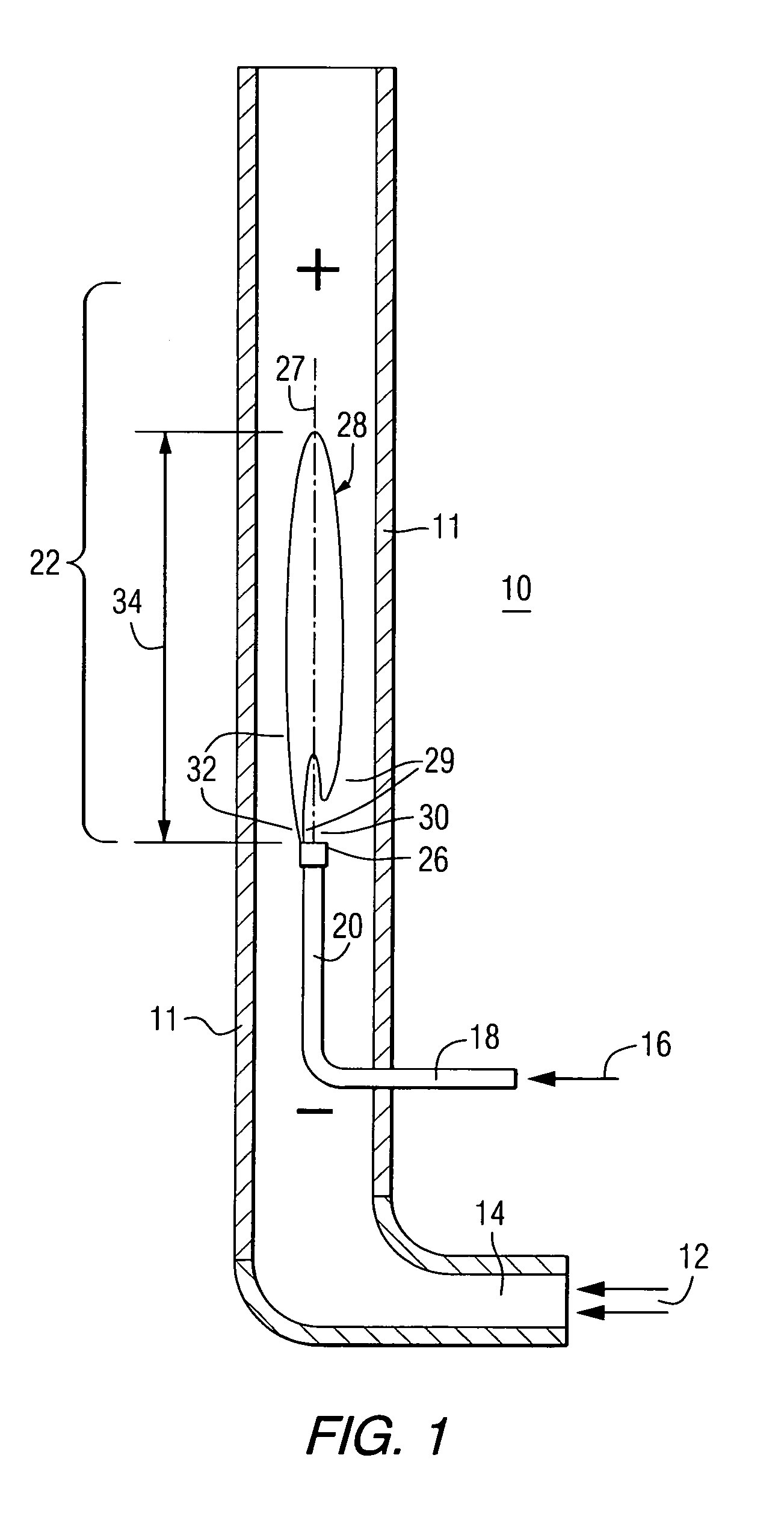
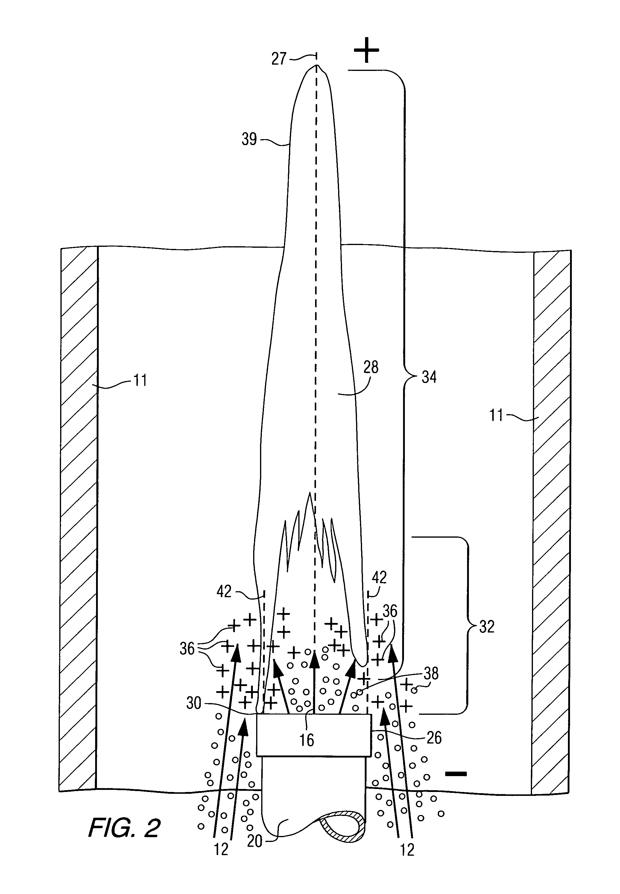
[0012]The invention also includes a method for mixing gaseous fuel and gaseous oxidant and combusting the mixture, prior to passing to a gas turbine comprising: feeding combustible gaseous fuel to an enclosed combustor through at least one fuel feed tube and providing at least one combustion flame within the enclosed combustor at the end of the fuel feed tube, the flame having a top flame tip and a bottom root end at the end of the feed tube; feeding gaseous oxidant to contact gaseous fuel near the combustion flame; and then providing an electric field in the region of the combustion flame; and then adjusting the velocity of the gaseous oxidant to provide turbulent flow and turbulent mixing with the gaseous fuel near the root end of the flame, to provide combustion and ionization of the gases at least at their contact interface; and then adjusting the electric field to provide a corona discharge to enhance ionization, and turbulent mixing of the gases which in turn improves combustion; and then passing the hot combusted mixed gases to a gas turbine. This method relates primarily to a diffusion flame process.
[0015]The gaseous oxidant is air and the preferred gaseous fuel is methane or a natural gas mixture of hydrocarbons. The volume ratio of methane to air is from about 1:5 to about 1:100, where the air is fed at sufficient velocity to cause turbulent mixing of the fuel. This process provides reduced emissions of nitrogen oxides.

Problems solved by technology

However, using electric fields to significantly impact high velocity turbulent flames has not been demonstrated.
275–298, concluded that it is not possible to change the burning velocity by more than about 5 m / s, therefore it was thought that as the gas velocity increases above this limit, electric fields become increasingly less effective.

Method used


Image

  • Electric flame control using corona discharge enhancement
  • Electric flame control using corona discharge enhancement
  • Electric flame control using corona discharge enhancement

Examples


example

[0034]An apparatus was set up to combust air and methane fuel at the end of a methane fuel feed tube concentric within an air feed tube, essentially as shown in FIG. 1. The apparatus had a positive electrode placed above the end of the fuel feed tube, which tube was given a negative charge to make it a negative electrode such that an electric (static) field was generated between the electrodes along a flame axis parallel to the apparatus walls and parallel to the fuel feed tube and oxidant entry combustor walls. The inside diameter of the apparatus was about 2.2 cm, the outside diameter of the fuel feed tube was 0.5 cm and the outside diameter of the circular positive electrode, placed within the apparatus and above the fuel feed tube was 1.9 cm; its distance above the fuel feed tube was 10.0 cm. Methane was passed through the fuel feed tube at a rate of about 1.9 standard cubic feet / minute (53.8 liter / min) and pressurized air was passed around the fuel feed tube within the walls of...


PUM


Abstract

A method of operating a combustor (10), to provide intimately mixed hot combusted gas (44) for a gas turbine (46), includes feeding gaseous oxidant (12) and gaseous fuel (16) into the combustor (10) near a combustion flame (28) which has a tip end (39) and a root end (29), where corona discharge occurs through adjustment of an electric field (34), and where the corona discharge causes ionized particles (36) to form and also causes intimate turbulent mixing of the gases.

Description

BACKGROUND OF THE INVENTION[0001]1. Field of the Invention[0002]The present invention relates to an electric field enhanced combustion stabilizer that utilizes an electric field and corona discharge to improve the mixing and combustion characteristics of combustor assemblies used in combustion turbines.[0003]2. Background Information[0004]Combustion turbines burn hydrocarbon fuels such as methane gas mixed with large volumes of air to power a turbine. The stability of the combustion and the chemical by-products, among other parameters, are dependent on how efficiently the gas is mixed with the air and the configuration of the burner elements. One example of a combustor to heat gas for a gas turbine generator is taught by U.S. Pat. No. 5,413,879 (Domeracki et al.).[0005]The concept of imposing an electric field with a combustion turbine combustor, to augment the mixing and configuration stabilizing elements appeared attractive based on relatively low pressure, low velocity experiment...

Claims


Application Information

Patent Timeline
Patent Type & Authority Patents(United States)
IPC IPC(8): F02C3/22F23D14/74F23R3/16F23R3/18F23C99/00
CPCF23C99/001F23D2209/20
Inventor PAVLIK, DENNISBRANSTON, DAVID WALTERLINS, GUENTERHAMMER, THOMAS
Owner SIEMENS ENERGY INC
Why Eureka
Try Eureka