Surface wave chemical detector using optical radiation

a surface wave chemical and optical radiation technology, applied in the direction of instruments, specific gravity measurement, separation processes, etc., can solve the problems of inability to distinguish between different chemical species, disadvantages of other mass sensors such as lamb and love wave sensors, plate wave resonators, quartz crystal microbalance (qcm), etc., and achieve the effect of reducing the number of chemically selective layers

Inactive Publication Date: 2007-07-17
UT BATTELLE LLC
View PDF13 Cites 11 Cited by
  • Summary
  • Abstract
  • Description
  • Claims
  • Application Information

AI Technical Summary

Benefits of technology

[0008]This invention gains chemical selectivity by exposing the surface with adsorbed chemical species (adsorbate) to certain wavelengths that are indicative of the species present. High sensitivity of surface waves is combined with chemical selectivity of absorption spectroscopy. This approach does not necessarily depend upon coatings, thus greatly improving selectivity and avoiding the long-standing issues related to degradation of external coatings.

Problems solved by technology

One important disadvantage of the above surface-wave sensor is its inability to distinguish between different chemical species.
This disadvantage also exists on other mass sensors such as the quartz crystal microbalance (QCM), plate wave resonator, and Lamb and Love wave sensors.
However, this chemically selective layer frequently does not provide good chemical selectivity except in rare cases, for example, biosensors based on antibody-antigen interaction or DNA hybridization.
With appropriate material, small changes in temperature can cause rather large changes in frequency, wave velocity, and phase.

Method used


Image

  • Surface wave chemical detector using optical radiation
  • Surface wave chemical detector using optical radiation

Examples


embodiment iii (fig.1)

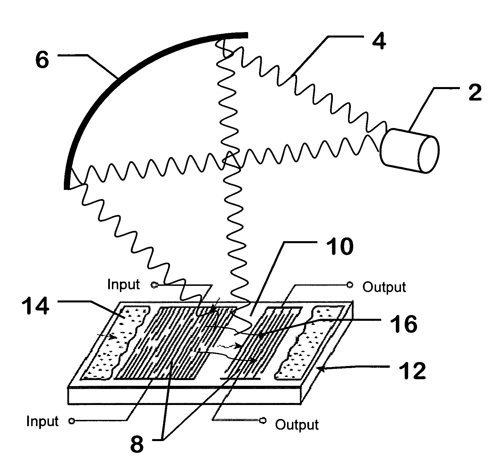
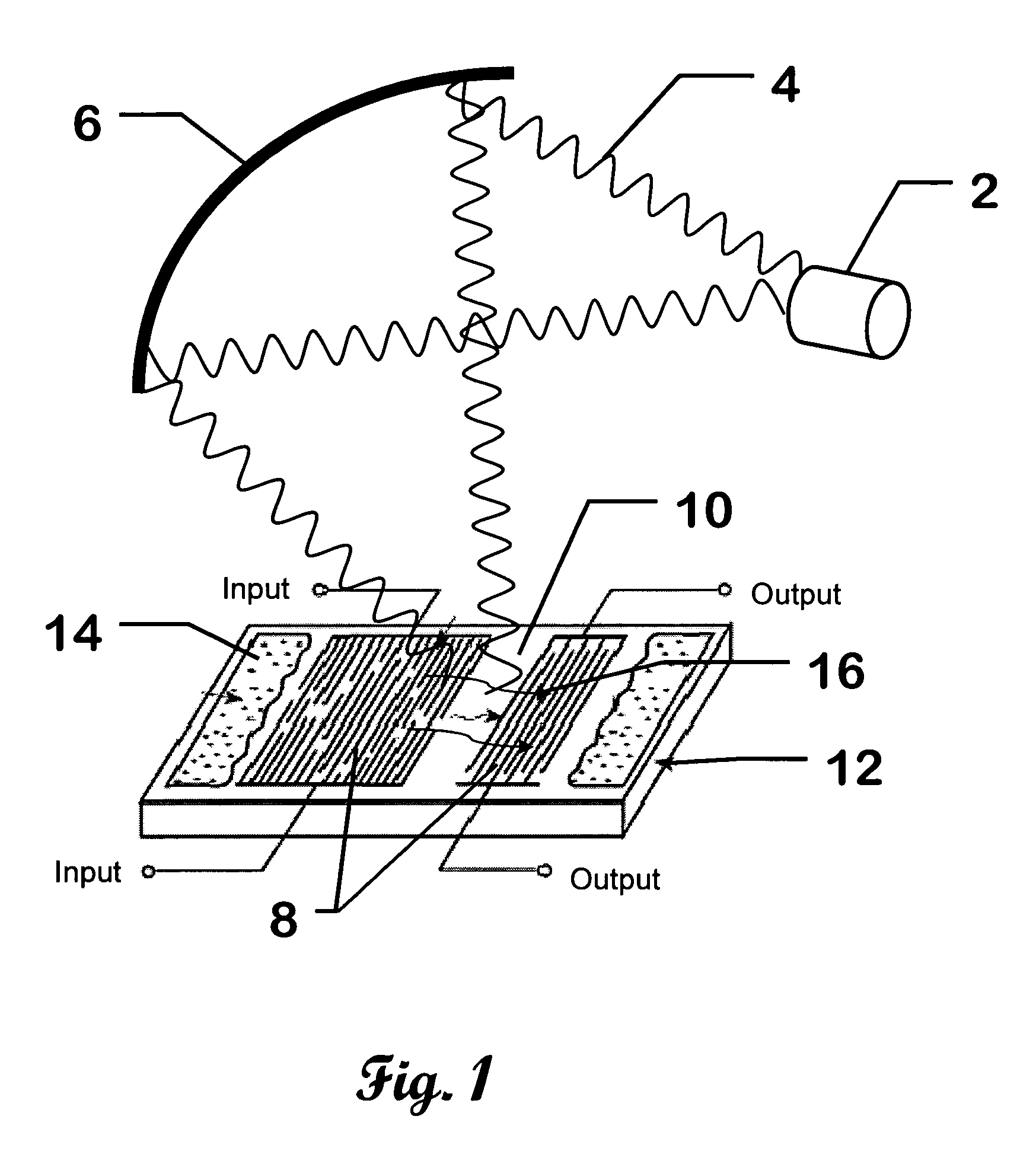
[0018]Embodiment III (FIG. 1): In this embodiment the surface waves 16 are created by focused pulsed radiation 4 on a piezoelectric substrate 12. The wavelength of the light is such that it can produce electron-hole pairs in the substrate 12. The substrate 12 can be a non-centro-symmetric crystal such as ZnO or GaAs. The surface inherently has a band bending. The light creates charge carriers that reach the localized illumination spot on the surface because of band bending. The charge then spreads out. An annular or lateral electrode placed around or near the illumination spot can detect the electronic waves created by the pulsed light. The presence of adsorbed species 14 on the surface can change the surface wave 16 velocity and other characteristics. Although such variations are sufficient to detect analytes, this method gives little chemical specificity. Again, chemical identification can be obtained by exposing the adsorbed molecules to optical radiation with wavelengths charact...


PUM

PropertyMeasurementUnit
frequencyaaaaaaaaaa
surface wave parameteraaaaaaaaaa
wavelengthsaaaaaaaaaa

Abstract

A surface wave chemical detector comprising at least one surface wave substrate, each of said substrates having a surface wave and at least one measurable surface wave parameter; means for exposing said surface wave substrate to an unknown sample of at least one chemical to be analyzed, said substrate adsorbing said at least one chemical to be sensed if present in said sample; a source of radiation for radiating said surface wave substrate with different wavelengths of said radiation, said surface wave parameter being changed by said adsorbing; and means for recording signals representative of said surface wave parameter of each of said surface wave substrates responsive to said radiation of said different wavelengths, measurable changes of said parameter due to adsorbing said chemical defining a unique signature of a detected chemical.

Description

CROSS-REFERENCE TO RELATED APPLICATIONS[0001]This application claims priority to U.S. Provisional Patent Application 60 / 560,135 filed Apr. 7, 2004, and is herein incorporated by reference.STATEMENT REGARDING FEDERALLY SPONSORED RESEARCH[0002]This invention was made with United States Government support under Contract No. DE-AC05-00OR22725 between the United States Department of Energy and U.T. Battelle, LLC. The United States Government has certain rights in this invention.BACKGROUND OF THE INVENTION[0003]It is well established that surfaces can support mechanical waves. Depending on the nature of the substrate, these surface waves are called Rayleigh waves, Lamb waves, and Love waves. Rayleigh waves are for thicker substrates while Lamb and Love waves are for thin membranes. The surface waves can be generated on a piezoelectric substrate using electrode arrays deposited on the surface. Once created, the wave travels on the surface and can be detected using a second electrode array....

Claims


Application Information

Patent Timeline
Patent Type & Authority Patents(United States)
IPC IPC(8): G01N30/00B01D15/04G01N29/02G01N29/04G01N29/24
CPCG01N29/022G01N29/2418G01N2291/0255G01N2291/0256G01N2291/0423G01N2291/0426G01N2291/0427
Inventor THUNDAT, THOMAS G.WARMACK, ROBERT J.
Owner UT BATTELLE LLC
Why Eureka
Try Eureka