
Extruder for producing bodies of consolidated particulate material

a technology of consolidated particulate material and extruder, which is applied in the field of extruder, can solve the problems of uncontrollable movement of dewatered and untreated materials, and the end product does not become fully homogeneous, and achieves the effects of collapsing or falling apart, and reducing the risk of deformation

Inactive Publication Date: 2007-07-17
3H INVENTORS APS
View PDF13 Cites 0 Cited by
  • Summary
  • Abstract
  • Description
  • Claims
  • Application Information

AI Technical Summary

Benefits of technology

[0006]It is the object of the present invention to provide an extruder of the kind referred to initially, with which it is possible to produce shaped bodies having a considerable mechanical strength, so that they can be handled or manipulated mechanically immediately upon completion of the final step of the extruder without any risk of deforming, collapsing or falling apart.
[0010]Thus, the apparatus as such commences in the form of high-pressure slurry pumping in one end of the mould and terminates as a powder-pressing process steadily progressing from the other end of the mould. It will be understood that in this case, the low-viscosity suspension will have no difficulty in flowing out into all nooks and crannies of the mould, and any air having been trapped during the filling-up of the mould will leave the mould cavity through its perforations together with the surplus liquid. The finished press-moulded object will constitute an accurate replica of the internal surfaces of the mould, and since the composite material already has solidified in the mould in the same moment as all surplus water has been squeezed out and mutual contact between the solid-matter particles has been achieved, it is now possible to remove the moulded object from the mould immediately just as with any other powder-pressing method or apparatus—since this object is now fully rigid and self-supporting and requires no more than being allowed to harden completely by hydration in a suitable manner.
[0013]The end product made by proceeding according to one of the embodiments of the extruder according to the invention is characterized by being exceptionally dense and with an absolute minimum of porosity and being highly homogeneous, and by, in the fully-hardened condition, to possess valuable physical properties comprising an optimum combination of strength and toughness.
[0015]During the terminal part of the pressing apparatus, during which the solid particles are closely wedged and pressed together, so that the material solidifies, the particles are also pressed firmly against all fiber surfaces—in certain cases even into the surfaces of the fibers—resulting in optimum bond between the fiber and the matrix material and hence optimum fiber effect in the end product.
[0018]After hardening, a correctly made BMC material produced according to the present invention will have a tensile stress-strain curve exhibiting so-called strain hardening, in which the tensile stress continues to increase—without any formation of visible or harmful cracks—even right up to a strain of 1-2% or more. Thus, the strainability (elasticity or flexibility if so preferred) of the matrix material has, by extreme utilization of the admixed fibers, been increased by a factor of 100 or more—and this without causing any damage to the composite material.
[0020]This is in itself extremely valuable and applies in general to the high-quality BMC materials mentioned above as produced by the apparatus according to the invention. Further, experience has shown that for so-called FRC material produced with a normal Portland-cement matrix, the network of micro-cracks formed in the manner referred to above (with possible crack lengths of approximately 0.5-1 mm or less, width typically 10-50 gm) after being formed shows a marked tendency to self-healing, so that the material in the presence of moisture will again be dense, and so that the material when again being tension loaded achieves its original rigidity and strength and may be subjected to increased stresses in the same manner as during the first loading, also here exhibiting a smooth stress-strain curve and a convincing strain hardening with steadily increasing tensile stresses up to an ultimate straining capacity of 1-2% or more before the stresses begin to decrease.

Problems solved by technology

If the squeezing-out of the liquid occurs at the same time over the whole surface of the mould, there is a risk that dewatered and un-dewatered material moves about uncontrollably in the moulding space with the result that the end product does not become fully homogeneous.

Method used


Image

  • Extruder for producing bodies of consolidated particulate material
  • Extruder for producing bodies of consolidated particulate material
  • Extruder for producing bodies of consolidated particulate material

Examples


Embodiment Construction

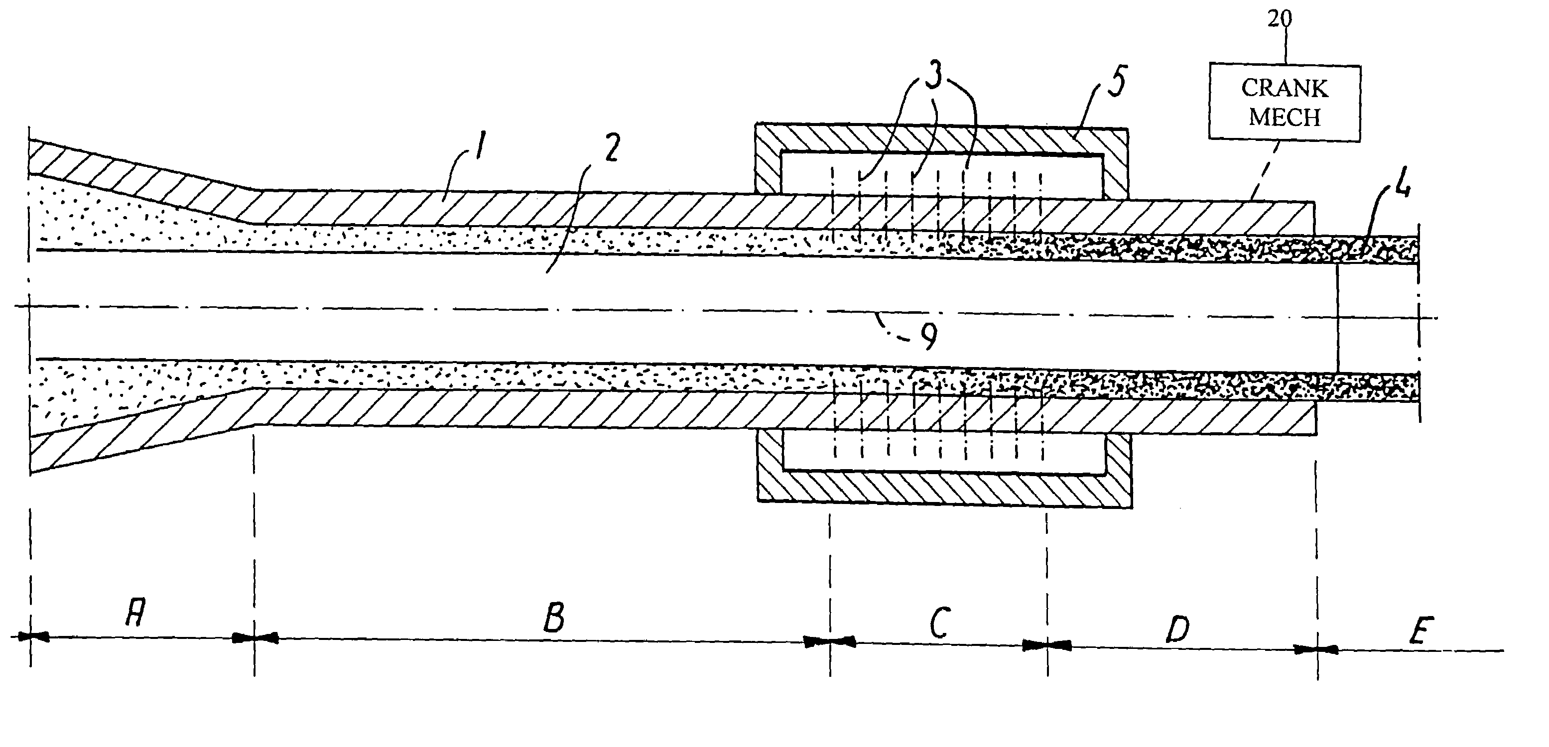
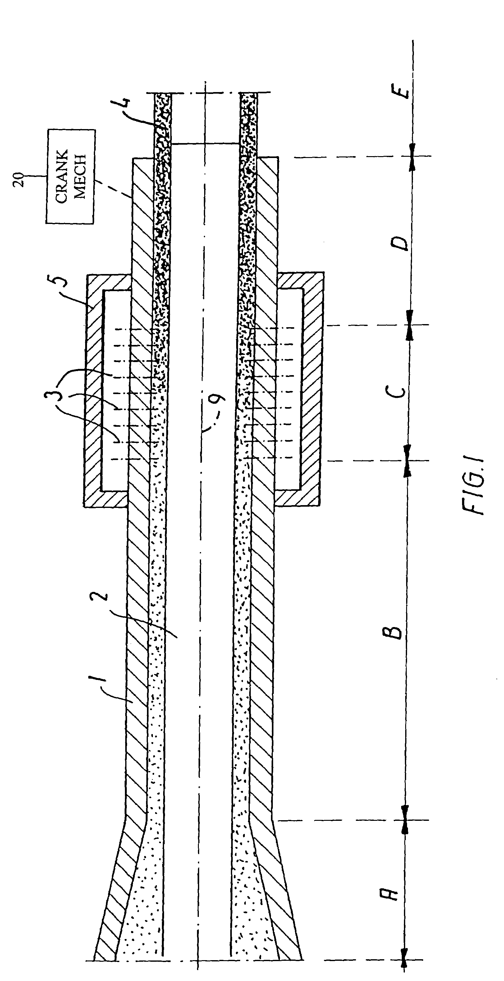
[0029]FIG. 1 shows the parts of an extruder essential to the invention, specially, designed for producing tubular products, it being obvious that an extruder based on the same principles could also be used for extruding products with other cross-sectional shapes, such as flat or corrugated sheets or profiled stock of various cross-sectional shapes.

[0030]The parts of the extruder shown comprise an outer part 1, an inner part 2, a plurality of nozzles or slits 3 for draining-off liquid, as well as a pressure-regulating chamber 5.

[0031]As shown, the extruder is divided into four consecutive sections, i.e.[0032]an inlet section A for the supply of flowable suspension to be compacted, and[0033]a flow section B, in which the suspension having been supplied flows towards[0034]a drainage and consolidation section C leading into[0035]a solid-friction section D.

[0036]Further, FIG. 1 shows a further section, designated the exit section E, in which the extruded product leaves the extruder.

[0037...


PUM

PropertyMeasurementUnit
pressureaaaaaaaaaa
widthaaaaaaaaaa
atmospheric pressureaaaaaaaaaa

Abstract

Shaped bodies of particulate material are produced by introducing an easily flowable slurry of water and particulate material into a mold with perforated walls and applying a sufficiently high pressure to the slurry in the mold so as to express a sufficient proportion of the liquid to allow physical contact and interengagement between the particles. The extrusion is carried out continuously in an extension process including: (A) introducing the slurry under high pressure, (B) conveying the slurry through a shaping section to (C) a draining and consolidation section with drain holds or slits (3), to leave the extruder through (E) an exit section in the form of a solid body (4).

Description

CROSS REFERENCE TO RELATED APPLICATION[0001]This application is a continuation of application Ser. No. 08 / 765,905, filed Jan. 7, 1997, now U.S. Pat. No. 6,398,998; which is a U.S. national phase of PCT / DK95 / 00296 filed Jul. 7, 1995.TECHNICAL FIELD[0002]The present invention relates to an apparatus, and particularly an extruder, for producing shaped bodies.BACKGROUND ART[0003]A method for producing shaped bodies and associated apparatus are disclosed in BE-A-653,349 and SE-B-304,711 (both based on FR priority application No. 955,561 of 29 Nov. 1963). In this known method, an unhardened mixture comprising hydraulic cement and aggregate material (sand and gravel) with surplus water is compressed in an extruder of constant cross-sectional shape by means of a reciprocating piston, and in the terminal part of said extruder, the walls of which are suitably perforated, part of the water is removed by applying a vacuum to the outside of said walls, all this taking place while the material is...

Claims


Application Information

Patent Timeline
Patent Type & Authority Patents(United States)
IPC IPC(8): B28B1/26B28B3/20B28B3/26B28B7/46
CPCB28B3/20B28B3/205B28B7/46
Inventor KRENCHEL, HERBERTFREDSLUND-HANSEN, HELGESTANG, HENRIK
Owner 3H INVENTORS APS
Learn More