
Plate for offset printing and method for manufacturing said plate

Inactive Publication Date: 2005-01-06
PLANCHAS Y PROD PARA OFFSET LITHOPLATE
View PDF6 Cites 2 Cited by
  • Summary
  • Abstract
  • Description
  • Claims
  • Application Information

AI Technical Summary

Benefits of technology

[0022] A first aspect of the present invention is to overcome the disadvantages mentioned by providing a plate for offset printing whose surface presents very good hydrophilicity and higher surface energy, as a result of its structure, which allows the contribution of water during its use to be reduced by up to 30%, and the isopropyl alcohol content in the wetting solution to be reduced by at least 50%. Said surface also has considerable mechanical strength, since up to 1,000,000 copies can be made, in relation to the ceramic substrate. The high chemical resistance shows itself in the resistance of its surface to uncontrolled oxidation, so that the protecting rubber on the plate is often unnecessary. It also has very good capacity for anchoring the light-sensitive varnishes due to the three-dimensional crosslinked structure, presenting an average roughness of the ceramic layer (Ra) from 0.3 to 0.9 μm.

Problems solved by technology

However, the mechanical and chemical resistance of said film is only slightly higher than the conventional anodised surfaces when the thickness of the ceramicised layer is very high, thus presenting problems of retention of the light-sensitive coating or greasing by mechanical stamping of ink into the surface structure during use of the plate.
Another noteworthy disadvantage of the printing plate according to EP 0514312 is that the surface obtained in silicate baths has a very high pH, which leads to alteration of the light-sensitive compounds placed on the surface to form the offset plate, even after energetic processes of washing the plate, due to the three-dimensional porous structure which characterises said films, hindering elimination of the alkaline remains and greater the thicker the film formed.
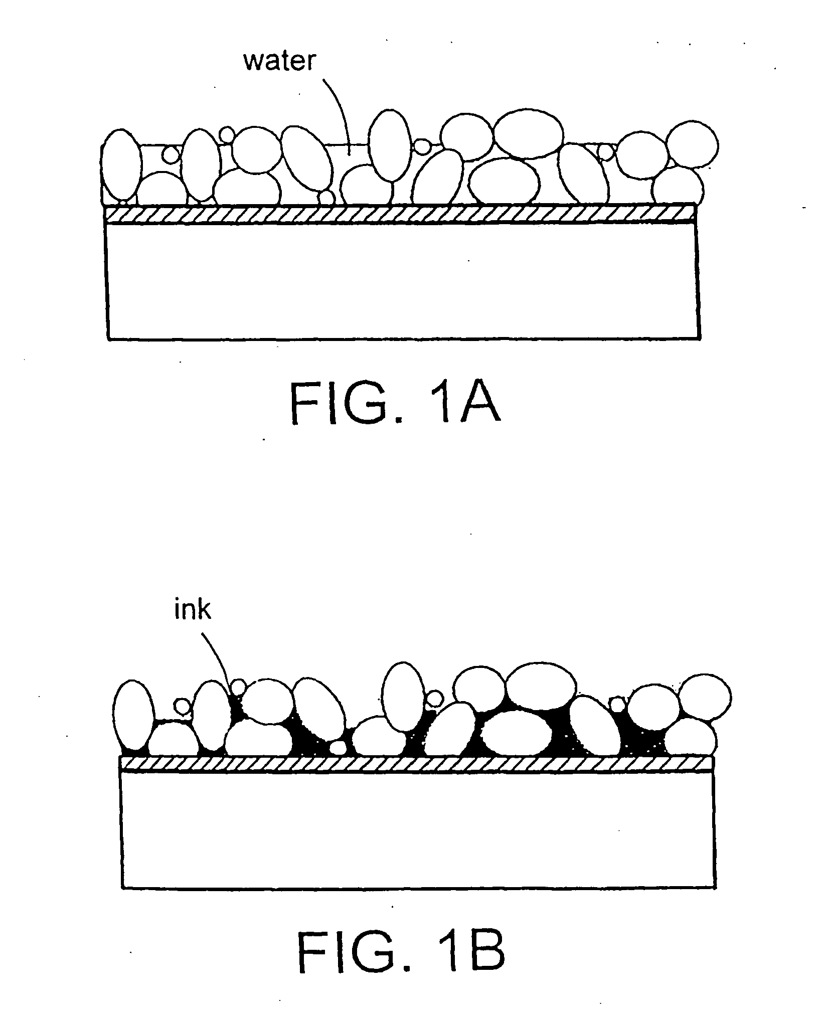
Yet another disadvantage is the fact that due to the high surface porosity of the ceramic layers of silicates inks are attracted into their cavities when there is insufficient water on their surface, a situation which arises quite frequently in the printing process.
Said ink is extraordinarily difficult to remove and often leads to the plate becoming useless due to a tendency to become greased (see FIG. 1).
Furthermore, a subsequent study carried out by the present applicant showed that it is not possible to develop ceramic films directly in sodium or potassium silicate baths, within the concentration limits stated in said European patent and for any initial state of the aluminium surface.
It is only possible to develop the ceramic plate satisfactorily if the aluminium surface initially has a non-greasy protective film, which prevents its dissolution caused by the high pH of the solutions used in the first steps of the procedure.
Also, in accordance with the process described in said European patent, if the aluminium surface has a zone protected by a greasy substance, no ceramicisation takes place on it unless the treatment is made enormously longer, in spite of which the surface is usually left non-uniform.
From this it can be deduced that the absence of grease on the aluminium surface must be ensured before ceramicising, but if, for example, alkaline solutions are used for degreasing, the form of natural oxide is removed from the surface of the aluminium and the ceramic layer cannot be built up.
For this reason, the initial state of the surface of the aluminium to be treated has an enormous influence on the result of the process, and becomes a problem for achieving regularity in the final characteristics of the plates obtained with this method.
Moreover, the electrolyte used according to the description of the aforesaid patent is alkaline, and when the bath becomes exhausted as a result of deposition of SiO2 on the surface of the aluminium, the concentration of NaOH or KOH increases and this means that the chemical aggressiveness of the bath increases and mounts a major attack on the aluminium itself.
This means that there is Al+3 in the bath, and that some of the bath has to be restored often, thus producing more waste effluent which has to be treated before it is disposed of.

Method used


Image

  • Plate for offset printing and method for manufacturing said plate
  • Plate for offset printing and method for manufacturing said plate
  • Plate for offset printing and method for manufacturing said plate

Examples


example 1

[0082] A strip of aluminium with a thickness of 0.14 mm and a width of 400 mm is taken. It is made to advance constantly at 5.0 m / min, while the anode is kept connected, through a first tank (first step of the treatment) where the bath is made up of a solution of potassium phosphate acid with a concentration of 10% by weight, ammoniumzirconium carbonate with a concentration of 19% by weight and ammoniumhafnium carbonate at 1% by weight in relation to the total of the solution.

[0083] The temperature of the bath is kept constant at 30° C. by means of a conventional heat evacuation system.

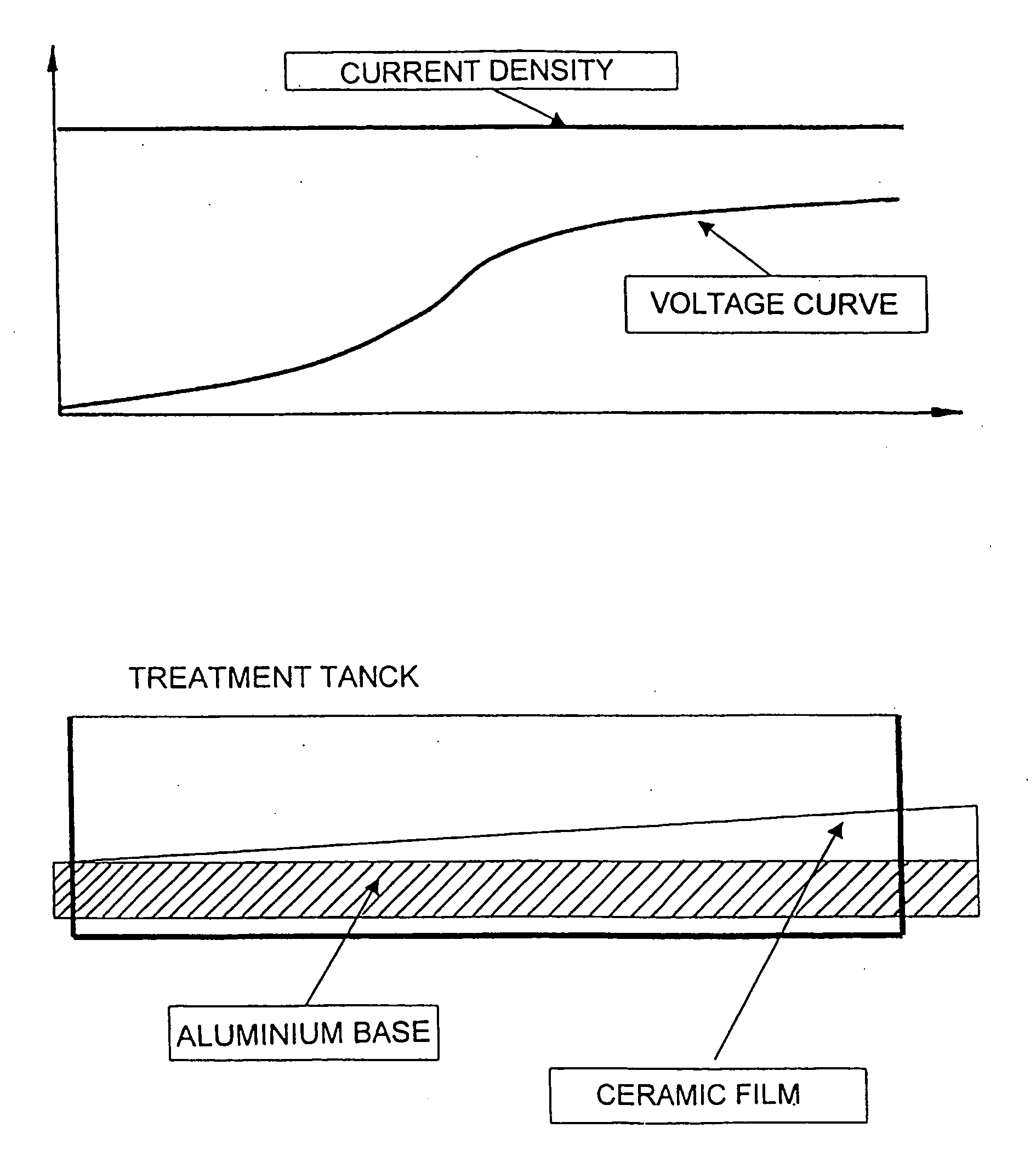
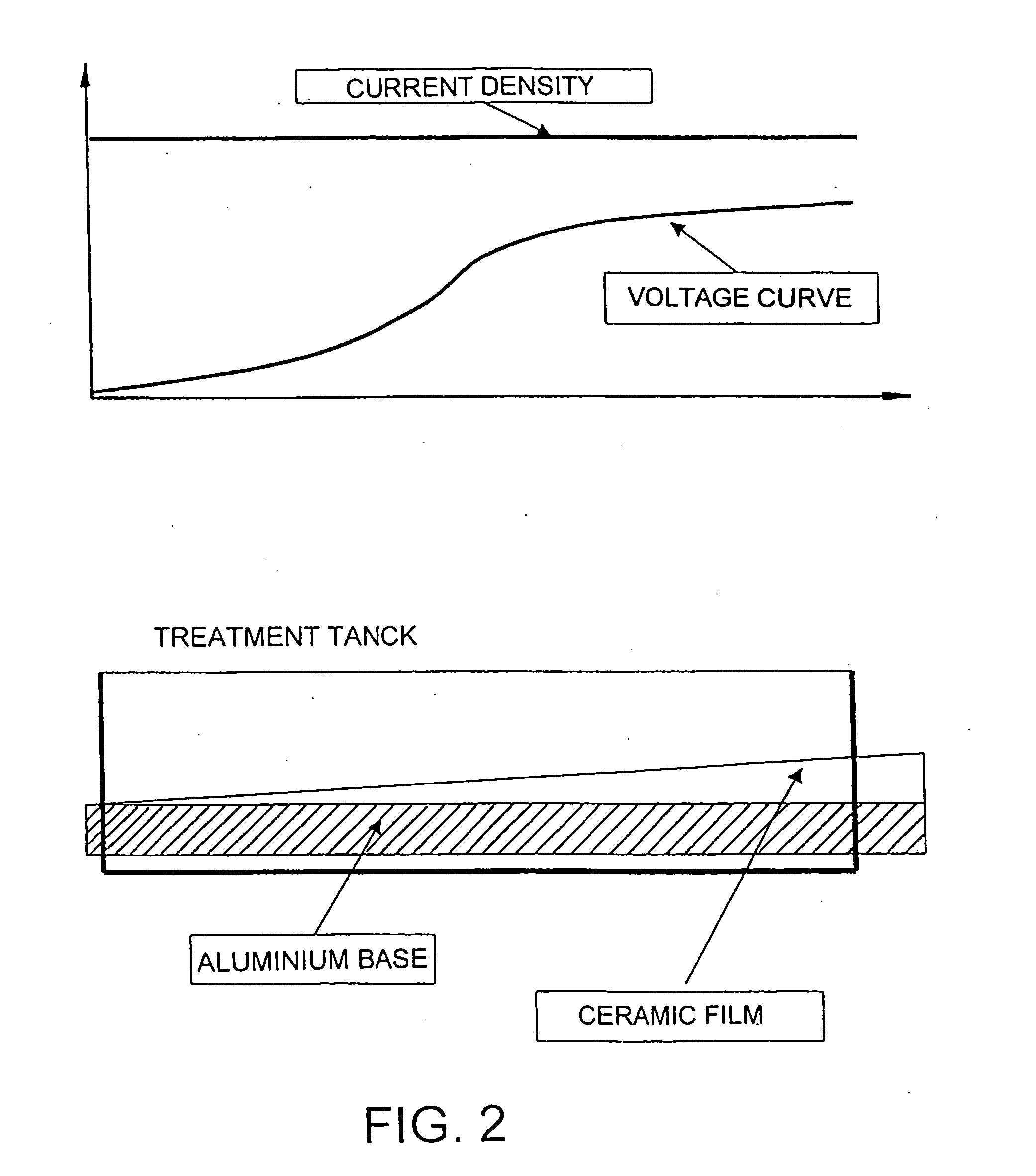
[0084] The strip of aluminium is gradually submitted, over the course of its travel through said tank, to a steady increase of voltage from 0 to 140 V, and from 120 V a clear white bubbling on the surface of the strip can be observed. When the treatment has been completed, the charge passed per unit of surface treated is 20 kC / m2. The resulting surface is whitish and uniform.

[0085] The strip is t...

example 2

[0094] A procedure similar to that described in example 1, but the composition of the bath of the first step was 15% by weight of ammonium—zirconium carbonate, 1% by weight of ammonium—hafnium carbonate and sodium tetraborate at 1% by weight in relation to the total of the solution. The need to provide 20% less water than usual was observed. 10,000 prints were made. Excellent results were obtained in the printing tests.

example 3

[0095] A procedure similar to that described in example 2, but the composition of the bath of the first step was 10% by weight of acid carbonate of ammonium, 10% by weight de aminoformiatoammonium and ammonium—zirconium carbonate at 6% by weight in relation to the total of the solution. The speed of the strip was 3.0 m / min. The need to provide 10% less water than usual was observed. 25,000 prints were made. Excellent results were obtained in the printing tests.


PUM

PropertyMeasurementUnit
Temperatureaaaaaaaaaa

Abstract

The plate includes an electrochemically anodisable metallic support of a thickness of 0.1-0.6 mm, carrying on one of its side a ceramic film of multilayer structure. The plate has greater hydrophillicity, resistance to chemical oxidation and to mechanical abrasion, and a lower surface tension that those of the prior art. The method comprises a first step in a bath containing sodium, potassium, ammonium or calcium borates, chlorides, carbonates and / or nitrates or forming mixed salts with elements of groups IIIB, IVB and VB, in a proportion of 5-40% by weight in relation to the total of the solution, at 20-60° C., 5-20 kC / m2 and 50-250 V; and a second step in a bath containing sodium, potassium or lithium phosphates, silicates and / or carbonates, in a proportion of 1-35% by weight in relation to the total of the solution, at 20-70° C., 5-25 kC / m2 and 150-400 V.

Description

FIELD OF THE INVENTION [0001] The present invention relates to a new plate for offset printing and to a method for manufacturing it. The plate according to this invention shows greater hydrophilicity and higher surface energy, and greater resistance to chemical oxidation and mechanical abrasion than the conventional plates. It also has excellent capacity for anchoring the light-sensitive varnishes placed on it. [0002] The manufacturing method consists in a unified treatment with lower generation of waste effluents than the conventional treatments, thereby providing a surface with very different and advantageous properties. BACKGROUND OF THE INVENTION [0003] Nowadays, 95% of the printing forms for offset to be found worldwide have an aluminium base, which base is submitted to a series of physical-chemical treatments in order to make its characteristics better suited to its subsequent use. Of such treatments, the main ones are the following: [0004] a) Degreasing; [0005] b) Mechanical,...

Claims


Application Information

Patent Timeline
IPC IPC(8): B41N1/00B41N1/08B41N1/20B41N3/03
CPCB41N1/006B41N1/08B41N3/038B41N3/034B41N1/20
Inventor GONZALES, ARELLANOMATA, HERNANDEZ LA
Owner PLANCHAS Y PROD PARA OFFSET LITHOPLATE
Learn More