
Computed radiography systems and methods of use

a radiography and computed technology, applied in the field of computed radiography, can solve the problems of limiting the amount of light that can be collected from the storage phosphor, unable to compensate for non-uniformities, and damage to the imaging plate to a point where it is no longer usabl

Active Publication Date: 2007-07-17
BAKER HUGHES INC
View PDF26 Cites 15 Cited by
  • Summary
  • Abstract
  • Description
  • Claims
  • Application Information

AI Technical Summary

Benefits of technology

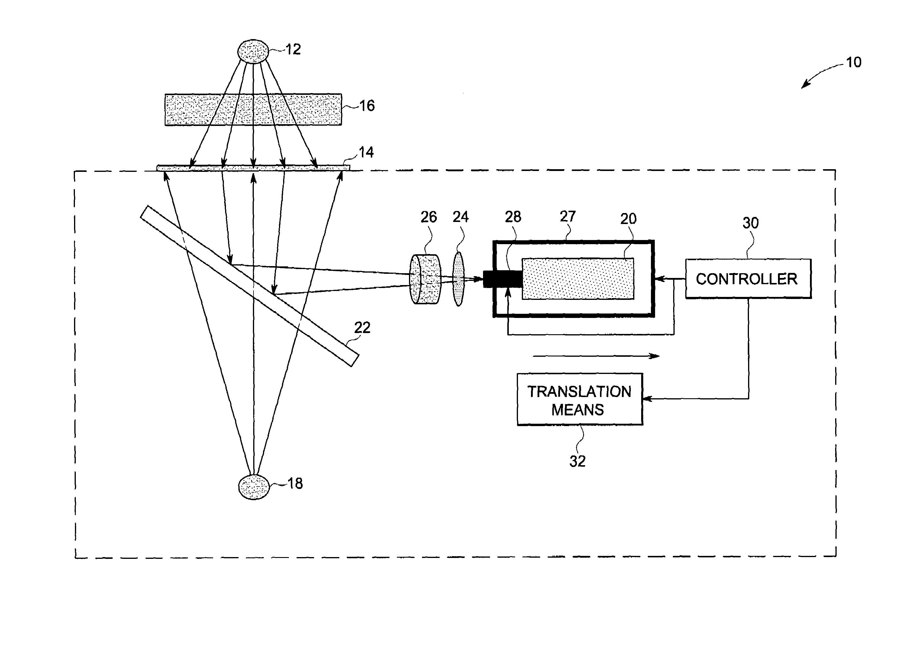
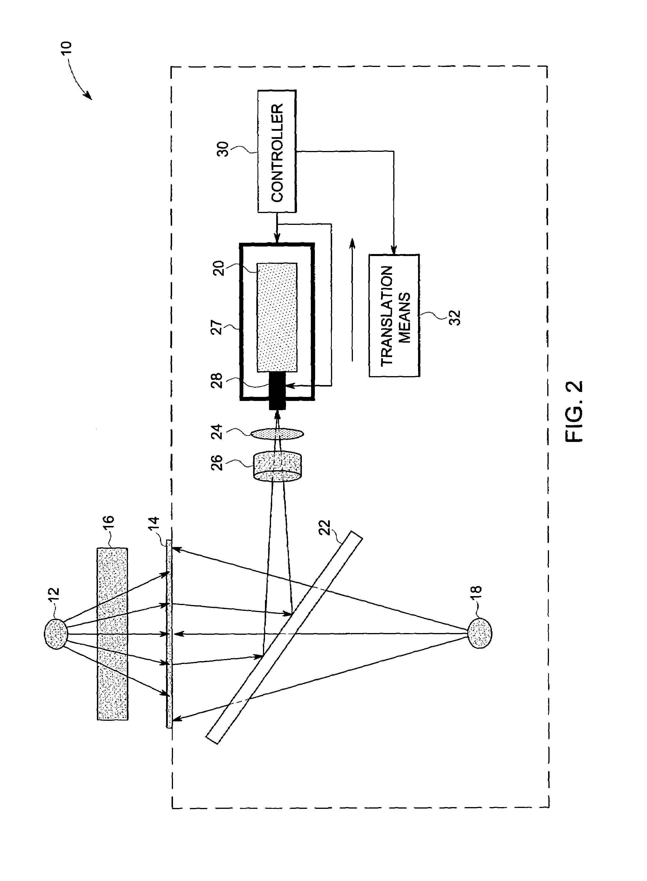
The patent describes a computed radiography (CR) system for imaging an object using a radiation source, a storage phosphor screen, an illumination source, and a two dimensional (2D) imager. The system can capture a 2D image of the object by illuminating the storage phosphor screen and capturing the emitted photons. The patent also provides a method for registering the storage phosphor screen and a method for retrieving a correction function associated with the screen. The technical effects of the patent include improved accuracy and efficiency in imaging objects using CR technology.

Problems solved by technology

This contact may eventually damage the imaging plate to a point where it is no longer usable.
The above scanning approaches limit the amount of light that can be collected from the storage phosphors as the residence time per pixel or per line is limited by a practical scan time taken for the imaging operation.
In addition, calibrations of these devices are one-dimensional (one row across the plate) and do not compensate for non-uniformities in the X-ray beam or phosphor granularity.
Therefore, much of the energy deposited onto the CR plates is lost due to failure to collect this prompt emission.
Further, in existing CR reading processes used to retrieve the stored emission information, some signal remains in the phosphor plate, which is typically wasted during the erasure cycle.
The X-ray energy losses due to prompt and non-retrieved stored emission reduce the detective quantum efficiency and signal to noise ratio for X-ray exposures that would otherwise result in a much higher image scan quality.
In nondestructive testing applications, this wasted energy results in longer throughput cycles for collecting imagery than otherwise desired.

Method used


Image

  • Computed radiography systems and methods of use
  • Computed radiography systems and methods of use
  • Computed radiography systems and methods of use

Examples


Embodiment Construction

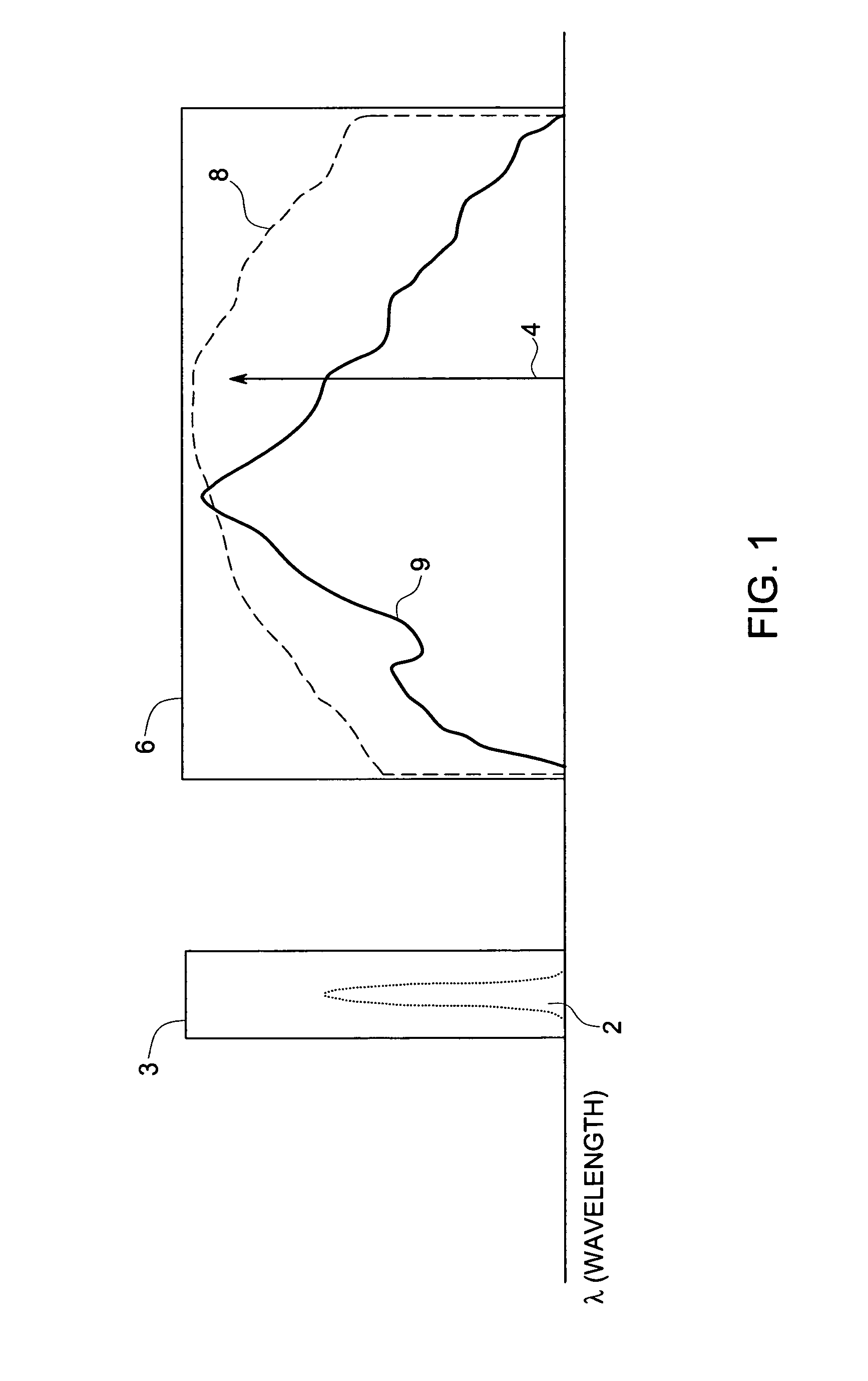
[0019]FIG. 1 is a graph illustrating the characteristic stimulation and emission behavior of a typical storage phosphor and the spectra of different stimulating light sources 4 and 8. As may be observed from FIG. 1, the desired stimulated and prompt emission spectra 2 and the stimulating excitation spectral band 6 have non-over lapping or disjoint wavelengths, thereby allowing the emission spectrum 2 (corresponding to the desired stored latent X-ray exposure pattern) to be recovered in the presence of the stimulating energy (envelope 6). Curve 9 shows the characteristic stimulation function for a typical storage phosphor. Conventional CR systems use a narrow band source (typically a laser) with characteristic spectrum 4 (shown through the use of an impulse-like function) to stimulate the storage phosphor to allow easier eventual separation of emission energy 2 in the presence of any stimulating energy 4. The total stimulating energy imparted to the phosphor is proportional to the pr...


PUM

PropertyMeasurementUnit
wavelengthaaaaaaaaaa
radiation energyaaaaaaaaaa
areaaaaaaaaaaa

Abstract

A computed radiography (CR) system for imaging an object is provided. The system includes a radiation source, a storage phosphor screen, an illumination source and a two dimensional imager. The radiation source is configured to irradiate the storage phosphor screen, and the storage phosphor screen is configured to store the radiation energy. The illumination source is configured to illuminate at least a sub-area of the storage phosphor screen to stimulate emission of photons from the storage phosphor screen. The two dimensional (2D) imager is configured to capture a two dimensional image from the storage phosphor screen using the stimulated emission photons. A method of reading a storage phosphor screen is also provided. The method includes illuminating at least a sub-area of the storage phosphor screen using an illumination source to stimulate emission of photons from the storage phosphor screen. The method further includes capturing at least one 2D image using a 2D imager, from at least a sub-array of the storage phosphor screen using the stimulated photons.

Description

BACKGROUND[0001]The invention relates generally to computed radiography (CR) systems and more particularly to a system and method for improving the scan speed and image quality in computed radiography systems.[0002]Computed radiography systems employ imaging techniques that capture X-rays as they pass through an object to be imaged using an imaging plate coated with a storage phosphor. The object to be imaged is typically exposed with X-rays, and a latent X-ray image is formed on the imaging plate. The storage phosphor on the imaging plate when stimulated with a low energy scanned light beam (such as a laser beam) releases visible light at locations where X-rays are absorbed. The light is then captured and converted into an electrical signal, which is subsequently converted to data that can be transmitted to remote systems or locations and displayed on laser-printed films or softcopy workstations and stored digitally.[0003]Traditionally, computed radiography scanning techniques empl...

Claims


Application Information

Patent Timeline
Patent Type & Authority Patents(United States)
IPC IPC(8): G01N23/04
CPCG01T1/2014
Inventor BUENO, CLIFFORDCORBY, JR., NELSON RAYMONDHERD, KENNETH GORDON
Owner BAKER HUGHES INC
Learn More