
Electrochromic or electrodeposition display and novel process for their manufacture

a technology of electrodeposition display and electrochromic display, which is applied in the field of electrochromic display and electrodeposition display, can solve the problems of inability to stabilize the electrochromic species, slow response rate, color fade, etc., and achieve the effects of reducing the occurrence of undesirable particle sedimentation, and reducing the viscosity of the electrolyte fluid

Active Publication Date: 2007-07-17
E INK CORPORATION
View PDF31 Cites 50 Cited by
  • Summary
  • Abstract
  • Description
  • Claims
  • Application Information

AI Technical Summary

Benefits of technology

The present invention is about an electrodeposition or elecromic display with microcups. The microcups are filled with an electrolyte fluid and individually sealed with a polymeric sealing layer. The microcups can be made by embossing a thermoplastic or thermoset precursor layer with a male mold, and the sealing can be done by dispersing a sealing composition in the electrolyte fluid or overcoating it with a sealing composition. The microcups can also contain density-matched reflecting particles to improve the display's response rate. The electrodeposition or elecromic display has advantages such as better mechanical properties, improved display performance when bent or under compression pressure, and the absence of an edge seal adhesive.

Problems solved by technology

Some of the drawbacks of this type of device are slow response rate due to the slow diffusion of redox active species towards the electrodes and low resolution and unacceptable stability of the electrochromic species for long-term operation.
Other disadvantages of this type of electrochromic devices include fading of color due to a certain degree of irreversibility of the diffused ion species to the metal oxide layer.
2)). However, all three types of electrochromic devices can only be manufactured by a batch-wise process and moreover their resolution and color addressability remain unsatisfactory for many applicat
Although the EDD described above addresses some of the drawbacks of the ECDs, such as the response time and contrast ratio, their usage is still limited due to certain problems.
In addition, the silver metal tends to deposit all over the electrode which results in a poor image resolution.
Although the image resolution may be improved by reducing the cell gap and optimizing the writing pulse width, color addressability of EDDs remains to be a major issue.

Method used


Image

  • Electrochromic or electrodeposition display and novel process for their manufacture
  • Electrochromic or electrodeposition display and novel process for their manufacture
  • Electrochromic or electrodeposition display and novel process for their manufacture

Examples


Embodiment Construction

I. Definitions

[0029]Unless defined otherwise in this specification, all technical terms are used herein according to their conventional definitions as they are commonly used and understood by those of ordinary skill in the art.

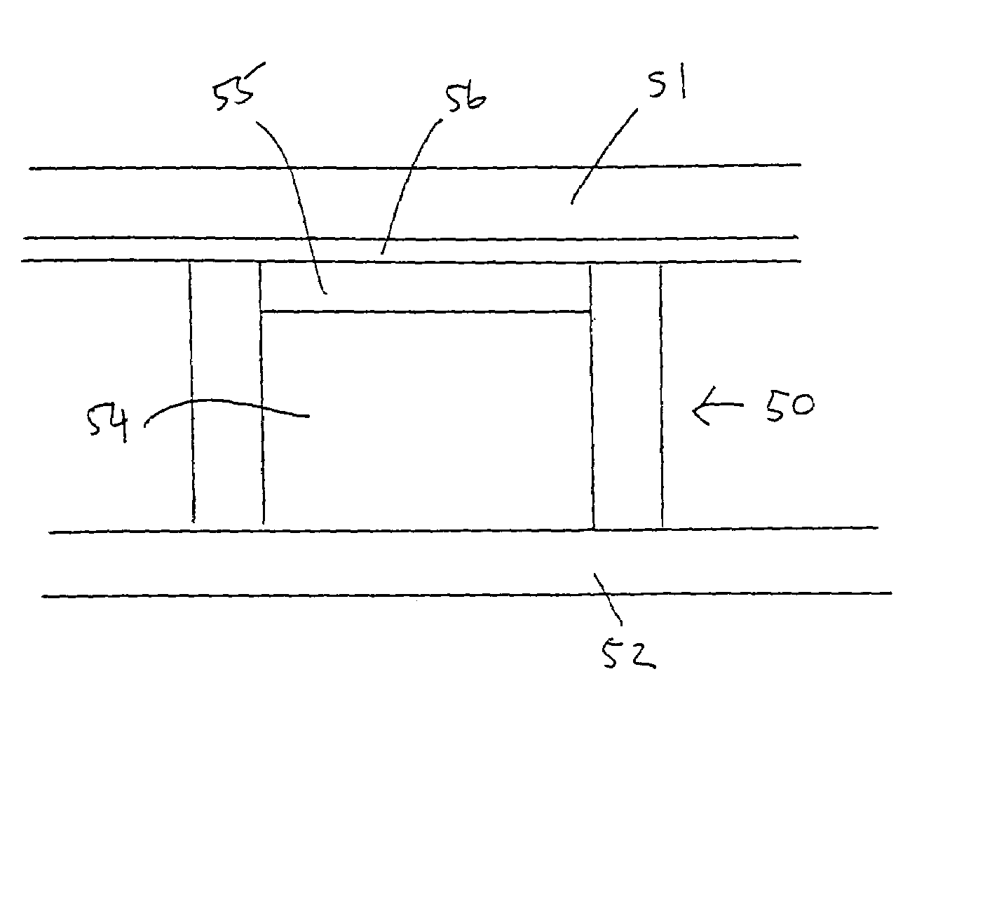
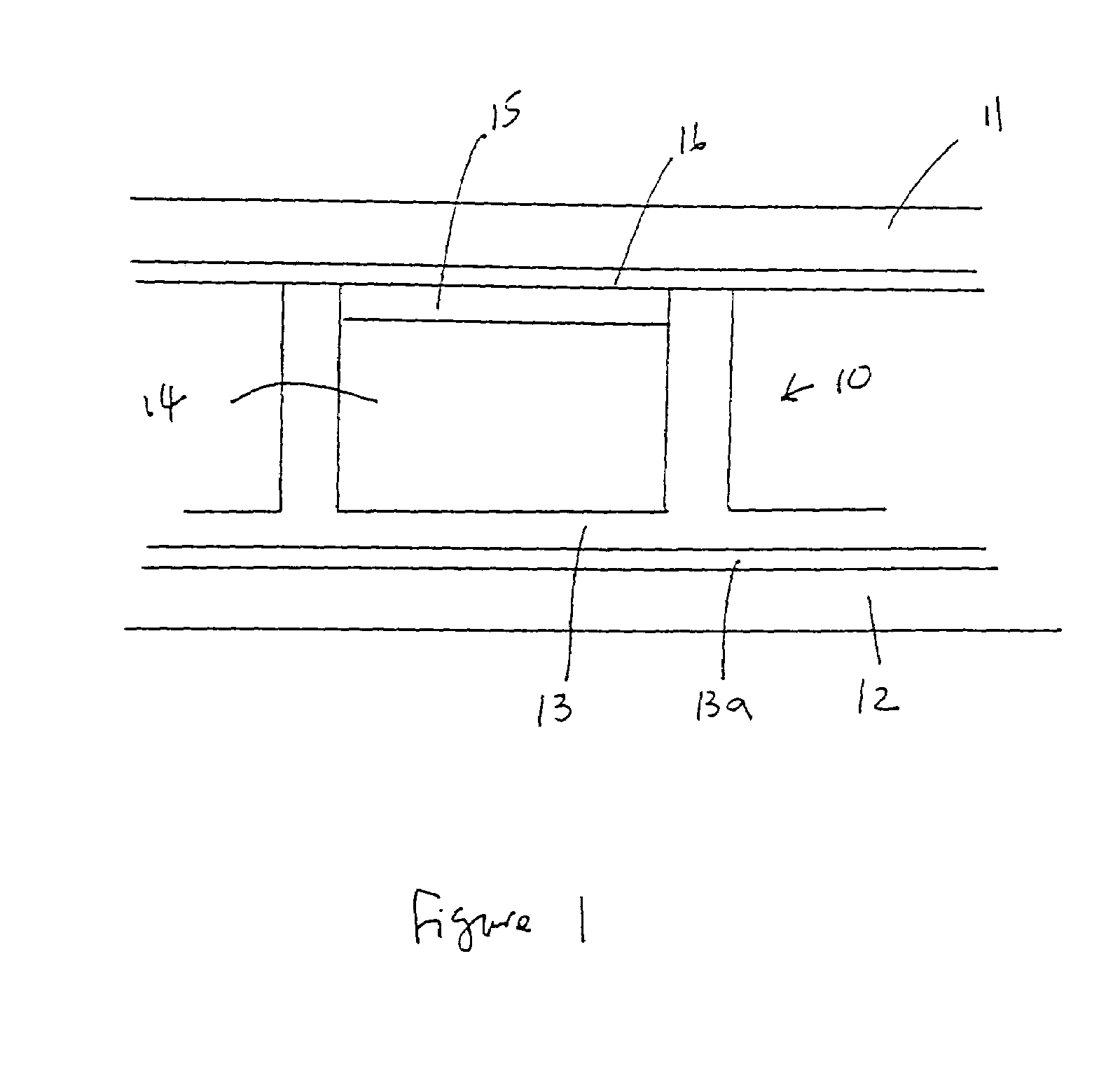
[0030]The term “microcup” refers to the cup-like indentations created by microembossing or imagewise exposure.

[0031]The term “cell”, in the context of the present invention, is intended to mean the single unit formed from a sealed microcup. The cells are filled with an electrolyte fluid.

[0032]The term “well-defined”, when describing the microcups or cells, is intended to indicate that the microcup or cell has a definite shape, size and aspect ratio which are pre-determined according to the specific parameters of the manufacturing process.

[0033]The term “aspect ratio” is a commonly known term in the art of displays. In this application, it refers to the depth to width or depth to length ratio of the microcups.

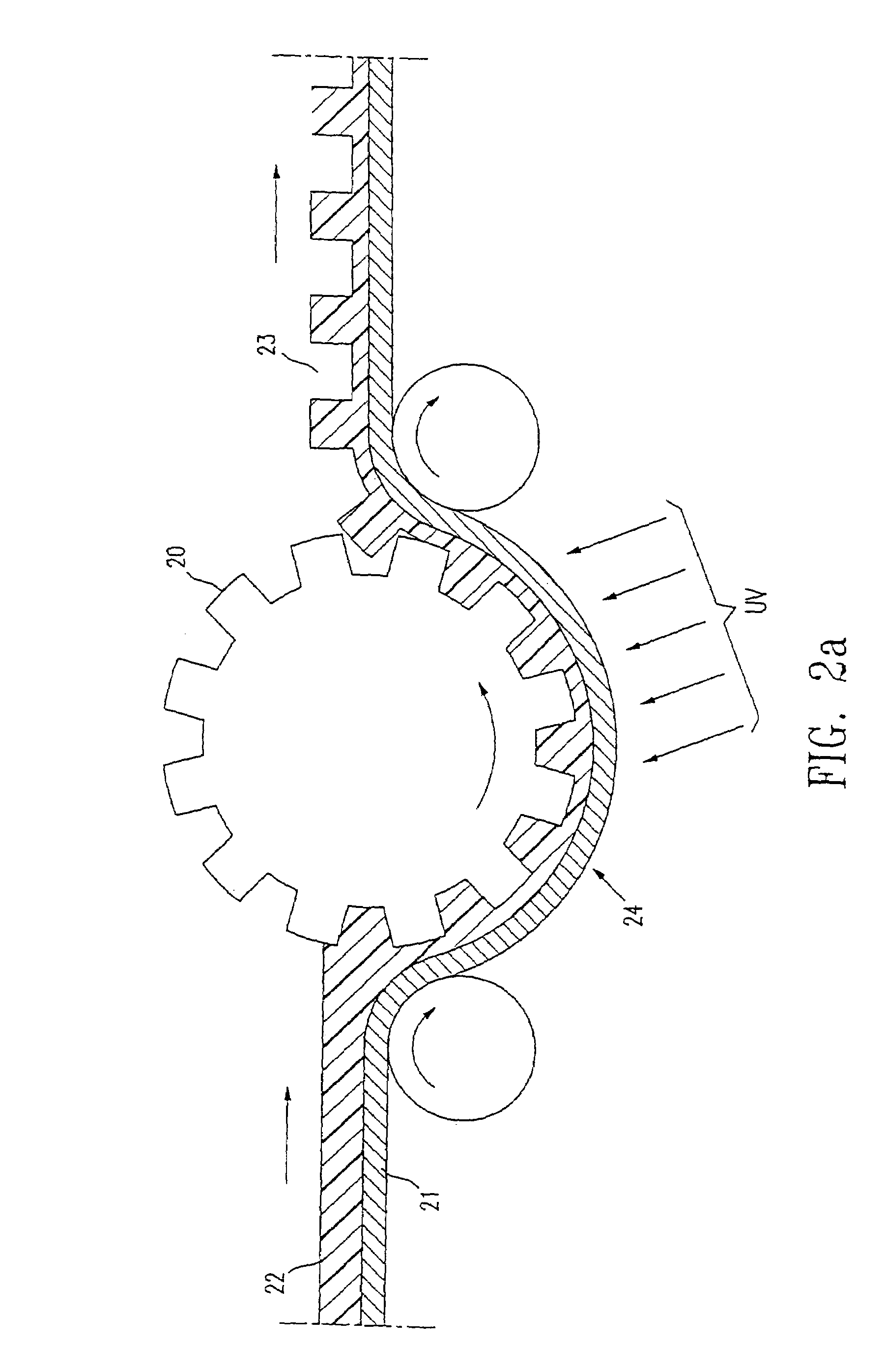
II Preparation of the Microcups

[0034]II (a) Preparat...


PUM

PropertyMeasurementUnit
thicknessaaaaaaaaaa
thicknessaaaaaaaaaa
temperatureaaaaaaaaaa

Abstract

The present invention is directed to an improved electrodeposition and an electrochromic display. The display cells formed from microcups are filled with an electrolyte fluid and are individually sealed with a polymeric sealing layer.

Description

RELATED APPLICATIONS[0001]This application claims the benefit of U.S. Provisional Application No. 60 / 409,833 filed Sep. 10, 2002, which is incorporated herein by reference in its entirety.BACKGROUND OF THE INVENTION[0002]1. Field of the Invention[0003]This invention relates to an electrochromic display (ECD) and an electrodeposition display (EDD), each comprising a plurality of isolated cells filled with an electrolytic fluid disposed between two electrodes.[0004]2. Description of Related Art[0005]Electrochemical displays, including electrochromic displays and electrodeposition displays, have been known for years and are attractive for portable display applications such as PDAs and e-books because they are reflective and may be driven at very low voltages. Electrochromic displays are non-light emission type display devices, the operation of which is based on reflection light or transmission light as a light control device through an electrochemical reaction and they broadly fall int...

Claims


Application Information

Patent Timeline
Patent Type & Authority Patents(United States)
IPC IPC(8): G02F1/15G02F1/1503G02F1/1506G02F1/153G02F1/161
CPCG02F1/133377G02F1/161G02F1/1523G02F1/1533G02F1/1506G02F1/1521G02F1/1503G02F1/153
Inventor LIANG, RONG-CHANGHOU, JACKANANTHAVEL, SUNDARAVEL P.
Owner E INK CORPORATION
Learn More