Optical element, optical lens, optical head apparatus, optical information apparatus, computer, optical information medium player, car navigation system, optical information medium recorder, and optical information medium server

Active Publication Date: 2007-07-24
PANASONIC CORP
View PDF43 Cites 10 Cited by
  • Summary
  • Abstract
  • Description
  • Claims
  • Application Information

AI Technical Summary

Benefits of technology

[0032]Therefore, with the foregoing in mind, it is an object of the present invention to provide an optical element, an optical lens, and an apparatus and a system adopting them, in which compatible reproducing and compatible recording of different kinds of optical disks are provided with a single objective lens, the change in focal length and the

Problems solved by technology

In this case, there is a problem that the generated amount of aberration is increased due to the incline (so-called tilt) of an optical axis.
Therefore, an unintended spherical aberration occurs and the light condensing ability is degraded.
Furthermore, in the case where it is attempted to realize the above-mentioned lens power by forming red light into diffused light as in the second conventional example, a large aberration occurs when the objective lens is moved by tracking or the like, and consequently, recording/reproducing characteristics are degraded.
Furthermore, it is di

Method used


Image

  • Optical element, optical lens, optical head apparatus, optical information apparatus, computer, optical information medium player, car navigation system, optical information medium recorder, and optical information medium server
  • Optical element, optical lens, optical head apparatus, optical information apparatus, computer, optical information medium player, car navigation system, optical information medium recorder, and optical information medium server
  • Optical element, optical lens, optical head apparatus, optical information apparatus, computer, optical information medium player, car navigation system, optical information medium recorder, and optical information medium server

Examples


embodiment 1

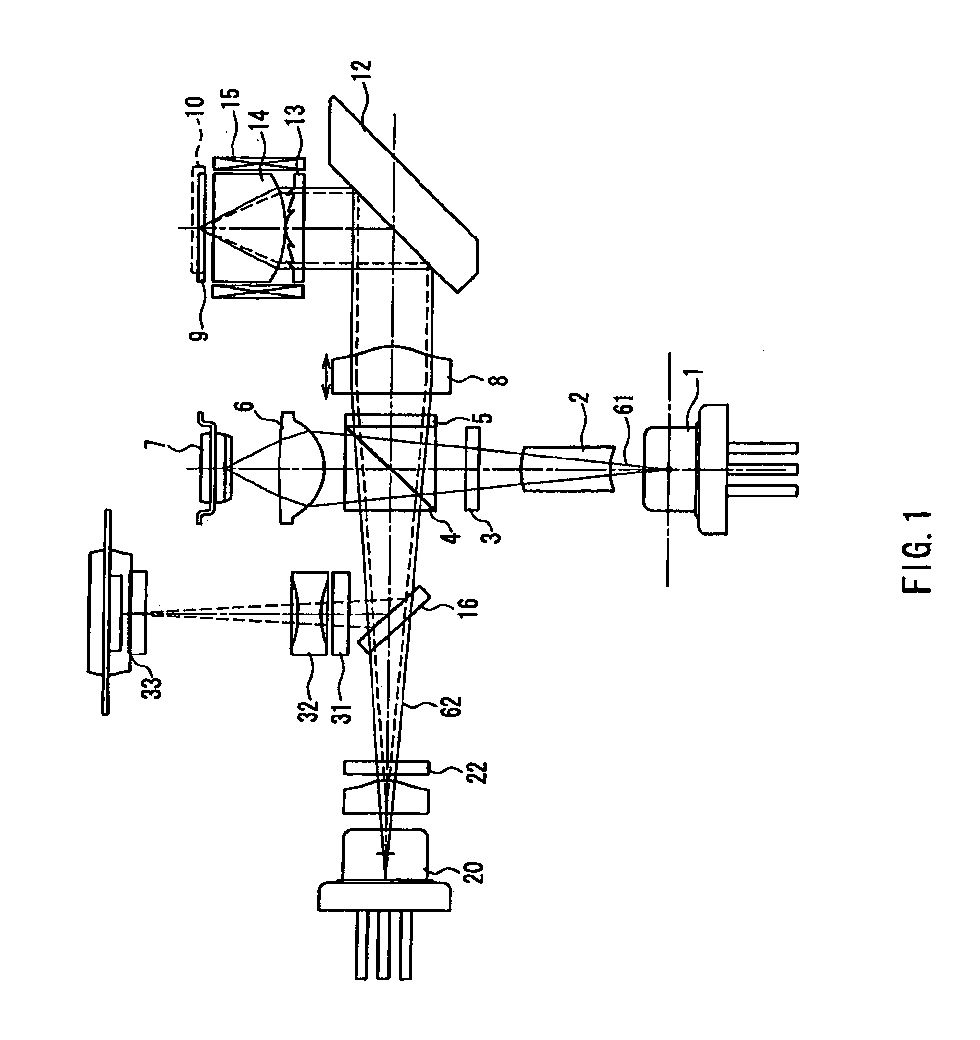
[0092]FIG. 1 is a schematic cross-sectional view of an optical head apparatus in Embodiment 1 of the present invention. In FIG. 1, reference numeral 1 denotes a blue laser light source that emits blue laser light with a wavelength λ1 (390 nm to 415 nm: generally, the wavelength λ1 is about 405 nm, so that the wavelength in a range of 390 nm to 415 nm will be collectively referred to as about 405 nm).

[0093]Reference numeral 20 denotes a red laser light source that emits red laser light with a wavelength λ2 (630 nm to 680 nm: generally, the wavelength λ2 is about 660 nm, so that the wavelength in a range of 630 nm to 680 nm will be collectively referred to as about 660 nm). Reference numeral 8 denotes a collimator lens (first convex lens), 12 denotes a mirror for allowing an optical axis to be deflected, and 14 denotes an objective lens (optical lens).

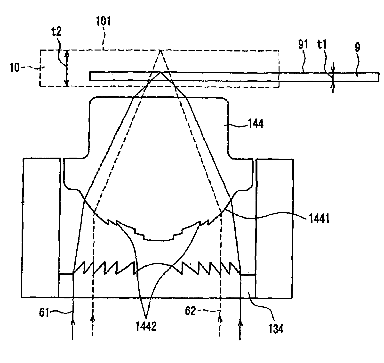
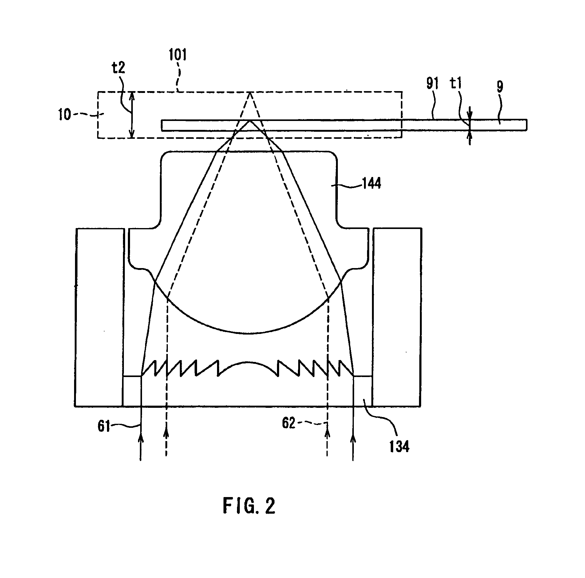
[0094]Reference numeral 9 denotes a third-generation optical disk corresponding to an optical information medium, which has a substrate...

embodiment 2

[0153]Next, Embodiment 2 of the present invention will be described. Embodiment 2 is the same as Embodiment 1, except that a cross-sectional shape of a grating in the inner circumferential portion 134C of the hologram 134 is changed. FIGS. 9A–9C illustrate a cross-sectional shape of a grating in one period in the inner circumferential portion 134C of the hologram 134 described in Embodiment 1. FIG. 9A shows a physical shape. FIG. 9B shows a phase modulation amount with respect to blue light. FIG. 9C shows a phase modulation amount with respect to red light.

[0154]In FIG. 9A, a vertical direction represents a height of a sawtooth shape grating. Unlike FIGS. 4A–4C, the height is determined based on a red light beam. Assuming that a hologram material is, for example, BK7, the refractive index nr of the hologram material with respect to a red light beam is 1.5142, with respect to a wavelength λ2 of 660 nm.

[0155]The height of the sawtooth shape grating is set so that the difference in opt...

embodiment 3

[0165]Embodiment 3 of the present invention will be described. In the same way as in Embodiments 1 and 2, an exemplary entire configuration of an optical head apparatus of Embodiment 3 is shown in FIG. 1. The configuration of a hologram in Embodiment 3 is different from that shown in FIG. 1, so that the function and configuration of a hologram that is a characteristic element in Embodiment 3 will be described with reference to FIGS. 10, 11A–11B, and 12A–12C.

[0166]In FIGS. 10, and 11A–11B, reference numeral 135 denotes a hologram. An inner circumferential portion 135C is, for example, the same as the inner circumferential portion 134C of the hologram 134 shown in Embodiment 1. FIGS. 12A–12C illustrate a cross-section in one period (p7) of a hologram grating in an outer circumferential portion 135B of the hologram 135. FIG. 12A shows a physical shape. FIG. 12B shows a phase modulation amount with respect to blue light. FIG. 12C shows a phase modulation amount with respect to red light...


PUM


Abstract

An optical lens includes a hologram, a refractive lens, and a phase level difference. The hologram has a sawtooth shape grating having a sawtooth shape in cross-section, and generates +2nd-order diffracted light most strongly with respect to blue light and +1st-order diffracted light most strongly with respect to red light, by setting a height of the sawtooth shape grating. The +2nd-order diffracted light of blue light is condensed through a substrate with a thickness t1, and the +1st-diffracted light of red light is condensed through a substrate with a thickness t2 (t1<t2). The difference in optical path length occurring when the blue light passes through the phase level difference is five times the wavelength of the blue light.

Description

BACKGROUND OF THE INVENTION[0001]1. Field of the Invention[0002]The present invention relates to an optical head apparatus and an optical information apparatus for recording / reproducing or erasing information recorded on an optical information medium such as an optical disk, a recording / reproducing method in an optical information apparatus, and a system adopting them. Furthermore, the present invention relates to an objective lens (optical lens) and a diffraction element used in the optical head apparatus, and a phase difference.[0003]2. Description of the Related Art[0004]An optical memory technique using an optical disk having a pit pattern as a recording medium with high density and high capacity is being widely used for a digital audio disk, a video disk, a document file disk, a data file, and the like, and is being put into practical use. The function of conveniently recording / reproducing information with respect to an optical disk with high reliability through a minutely cond...

Claims


Application Information

Patent Timeline
IPC IPC(8): G02B5/18G02B27/44G11B7/00G11B7/09G11B7/135
CPCG02B5/1842G02B27/4238G02B27/4277G02B27/4294G11B7/1367G11B7/1369G11B7/1374G11B7/13922G11B7/13925G11B7/1353G11B7/0948G11B2007/0006
Inventor KOMMA, YOSHIAKIMIZUNO, SADAOTANAKA, YASUHIRO
Owner PANASONIC CORP
Why Eureka
Try Eureka