Throughput in multi-rate wireless networks using variable-length packets and other techniques

a wireless network and variable-length packet technology, applied in the field of wireless networks, can solve the problems of limiting throughput for high data rate users, negating the benefit of high data rate for fast users, and high data rate users not realizing the benefit of their faster data rate. to achieve the effect of optimizing throughput in the network

Inactive Publication Date: 2007-07-24
IPR LICENSING INC
View PDF4 Cites 107 Cited by
  • Summary
  • Abstract
  • Description
  • Claims
  • Application Information

AI Technical Summary

Benefits of technology

[0026]Another technique to optimize throughput in the network is to fix the packet length but vary the contention window (CW) size for each user, so that low rate users will be less likely to win a channel contention than high rate users.

Problems solved by technology

Consequently, the low data rate users may have a disproportionately higher percentage of medium access time than high data rate users, which limits throughput for the high data rate users.
As this example shows, the slow users take much longer to transmit their packets than the fast users, effectively negating the benefit of the higher data rate for the fast users.
The high data rate users do not realize the benefit of their faster data rates because throughput is limited by the slowest user data rate.
As more users access the network, the access time increases, and at some point (approximately 50% utilization), the access time increases exponentially. FIG. 2 illustrates that throughput for all users on the network can become unacceptable as the network utilization increases, particularly with slow users, and at some the network may collapse completely.
Network administrators struggle with techniques to prevent network collapse.

Method used


Image

  • Throughput in multi-rate wireless networks using variable-length packets and other techniques
  • Throughput in multi-rate wireless networks using variable-length packets and other techniques
  • Throughput in multi-rate wireless networks using variable-length packets and other techniques

Examples


Embodiment Construction

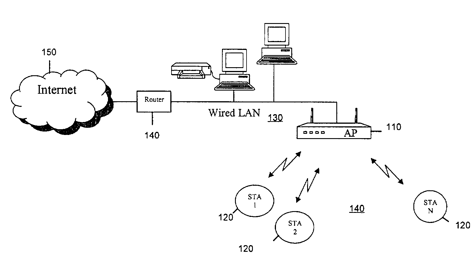
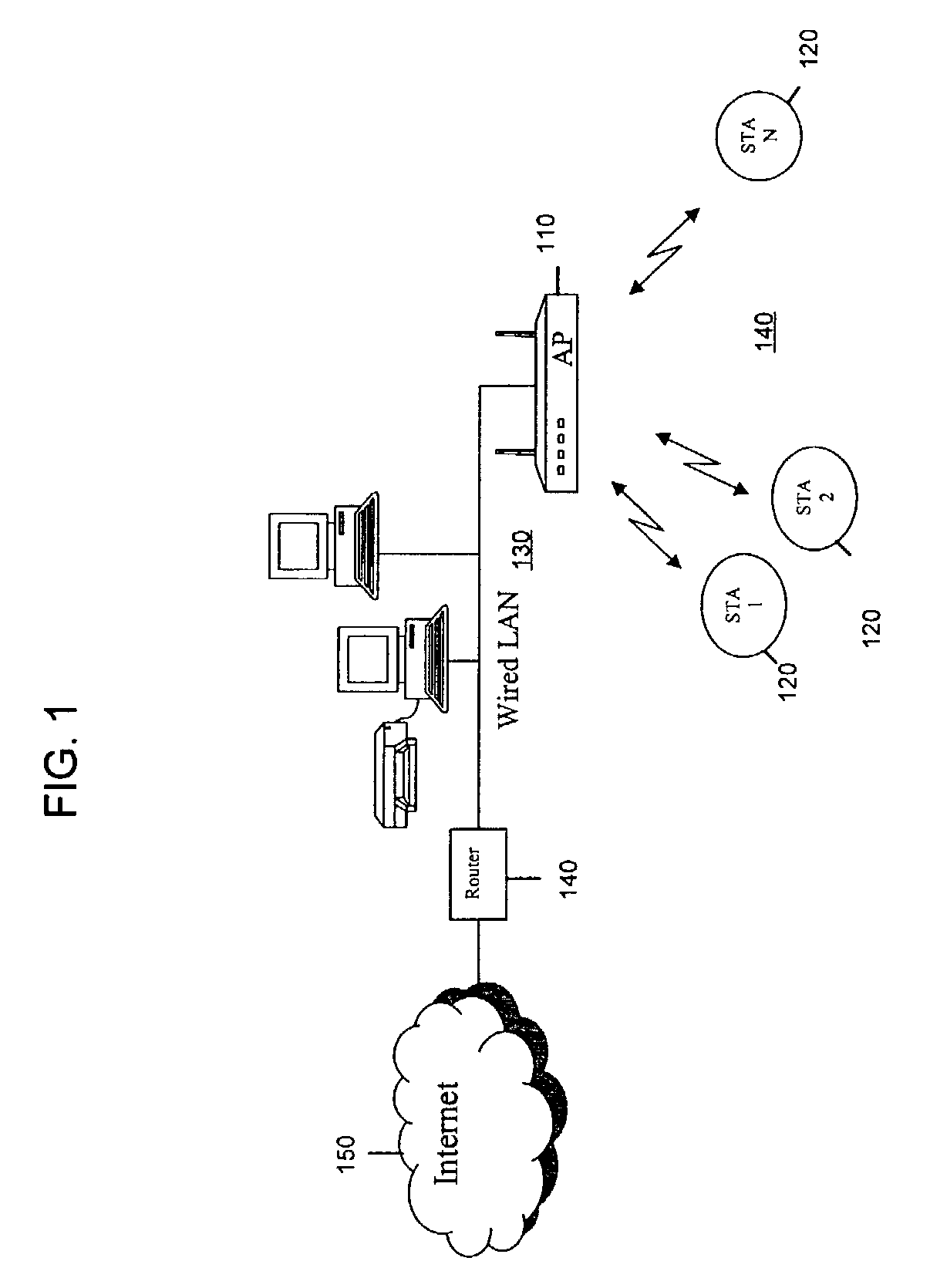
[0035]FIG. 1 illustrates an exemplary system where a wireless local area network (WLAN) 100 consisting of an access point (AP) 110 and a plurality of stations (STAs) (STA1–STAN) 120. The AP 110 may interconnect to a wired LAN 130, and ultimately, through a router 140, to the Internet 150.

[0036]FIG. 3 illustrates an exemplary AP 110 and a STA 120. In general, the AP 110 comprises a control processor 112, a baseband signal processor 114 and a radio transceiver 116. (it should be understood that the control processor 112 and the baseband signal processor 114 may be implemented on a single processing device.) The AP 110 receives signals from, and transmits signals to, the STAs 120 via one or more antennas 118. The processor 112 routes the received data from the STAs, and also directs outgoing data to the appropriate STA. In addition, the processor 112 in the AP 110 may execute a network throughput control process, described hereinafter, to control the average throughput on the WLAN 100....


PUM


Abstract

In a wireless communication network having a plurality of devices operating at different data rates that contend for access to the network, a method is provided that assigns network access parameters to one or more of the devices so as to control throughput on the network. Examples of network access control parameters are the maximum data packet size and the contention window size. Generally, the network access control parameter for slower data rate users is configured so that they do not occupy the network a disproportionate amount of time compared to faster data rate users.

Description

BACKGROUND OF INVENTION[0001]This application claims priority to U.S. Provisional Patent Application No. 60 / 330,755, filed Oct. 30, 2001, the entirety of which is incorporated herein by reference.[0002]The present invention is directed to wireless networks, and particularly to optimizing throughput among multiple data rate communication devices in a wireless network.[0003]In a wireless network, such as a wireless local area network (WLAN) that uses the IEEE 802.11x standard, communication devices that act as what is called in 802.11 parlance, stations (STAs), may use multiple data rates (e.g., 1, 2, 5.5, 11, . . . 54 Mbps) when communicating with a communication device that acts as what is called in 802.11 parlance, an access point (AP). The data rate assigned to a STA may be based on its proximity to the AP. For example, devices closer to the AP typically operate at faster data rates than devices further from the AP. Each frequency channel of 802.11 may be shared, via carrier sense...

Claims


Application Information

Patent Timeline
Patent Type & Authority Patents(United States)
IPC IPC(8): H04J3/16H04L12/28H04L12/56
CPCH04L12/5695H04L47/10H04L47/15H04L47/762H04L47/765H04L47/822H04L47/824H04L47/826H04W28/12H04W28/22H04W84/12H04L47/70H04L1/0007
Inventor SUGAR, GARY L.SEED, WILLIAM R.COLLINS, ANTHONY T.
Owner IPR LICENSING INC
Why Eureka
Try Eureka