
Systems and methods for transmitting quantum and classical signals over an optical network

a quantum and optical network technology, applied in the field of optical networks and quantum cryptography, can solve the problems of introducing errors that reveal her presence, affecting the detection of quantum signals, and complicating the qkd process, so as to reduce optical noise

Active Publication Date: 2007-07-24
MAGIQ TECH INC
View PDF17 Cites 84 Cited by
  • Summary
  • Abstract
  • Description
  • Claims
  • Application Information

AI Technical Summary

Benefits of technology

"The invention relates to a method and system for transmitting classical and quantum signals over a network using optical fibers. The method involves filtering the classical signals to remove wavelengths that may interfere with the quantum signals, and narrow-filtering the quantum signals to remove spurious non-quantum signals that may cause false detector counts. The system includes a demultiplexer to separate the quantum and classical channels, and optical isolators, amplifiers, and filters to improve the signal-to-noise ratios of the quantum signals. The technical effects of the invention include improved signal-to-noise ratios and reduced interference between classical and quantum signals, which can enhance the security and reliability of optical communication networks."

Problems solved by technology

As a consequence, an eavesdropper (“Eve”) that attempts to intercept or otherwise measure the exchanged qubits will introduce errors that reveal her presence.
This complicates the QKD process because detecting the quantum signals is hampered by the presence of the classical signals as well as the relatively large amounts of noise they generate in the quantum channel.

Method used


Image

  • Systems and methods for transmitting quantum and classical signals over an optical network
  • Systems and methods for transmitting quantum and classical signals over an optical network
  • Systems and methods for transmitting quantum and classical signals over an optical network

Examples


Embodiment Construction

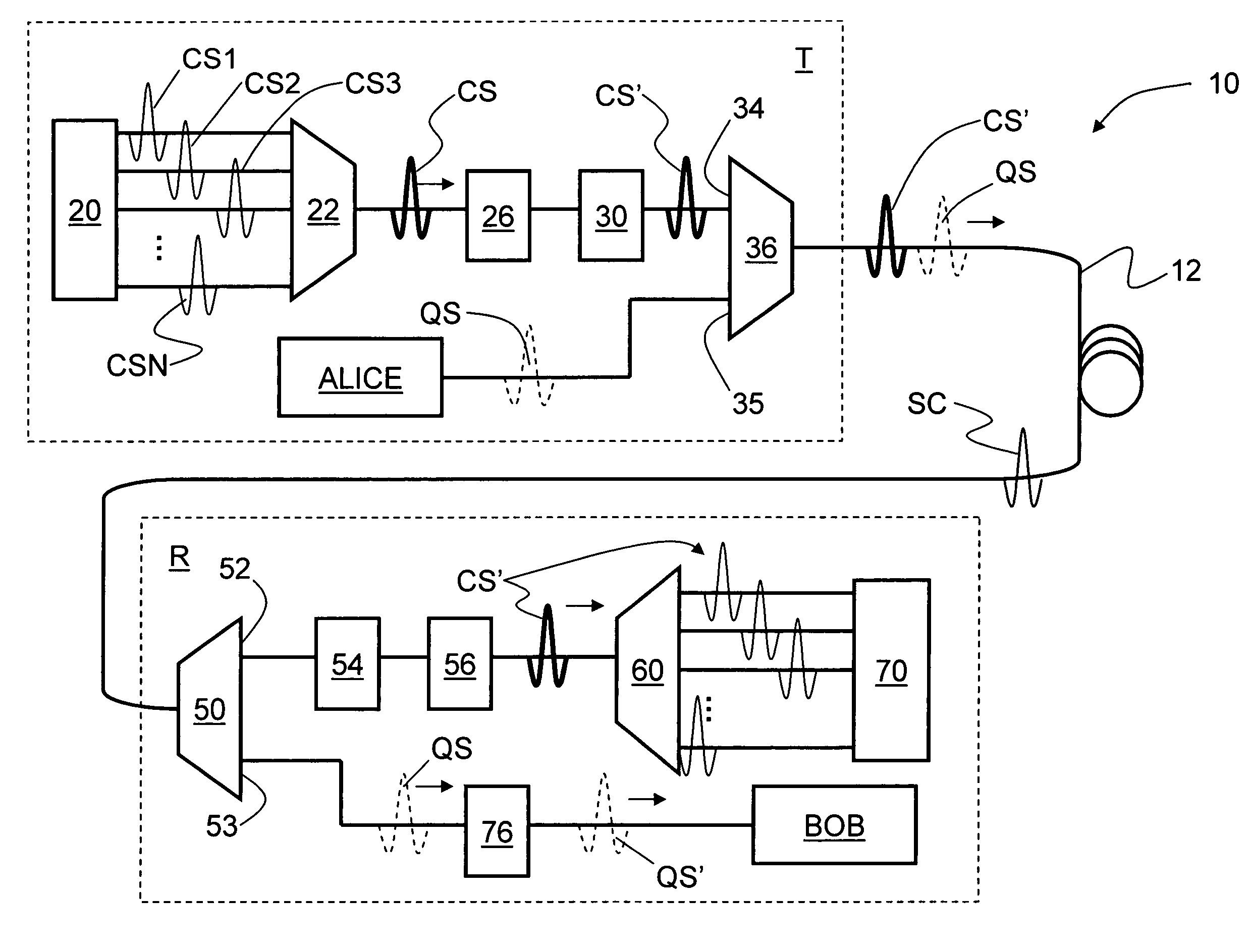
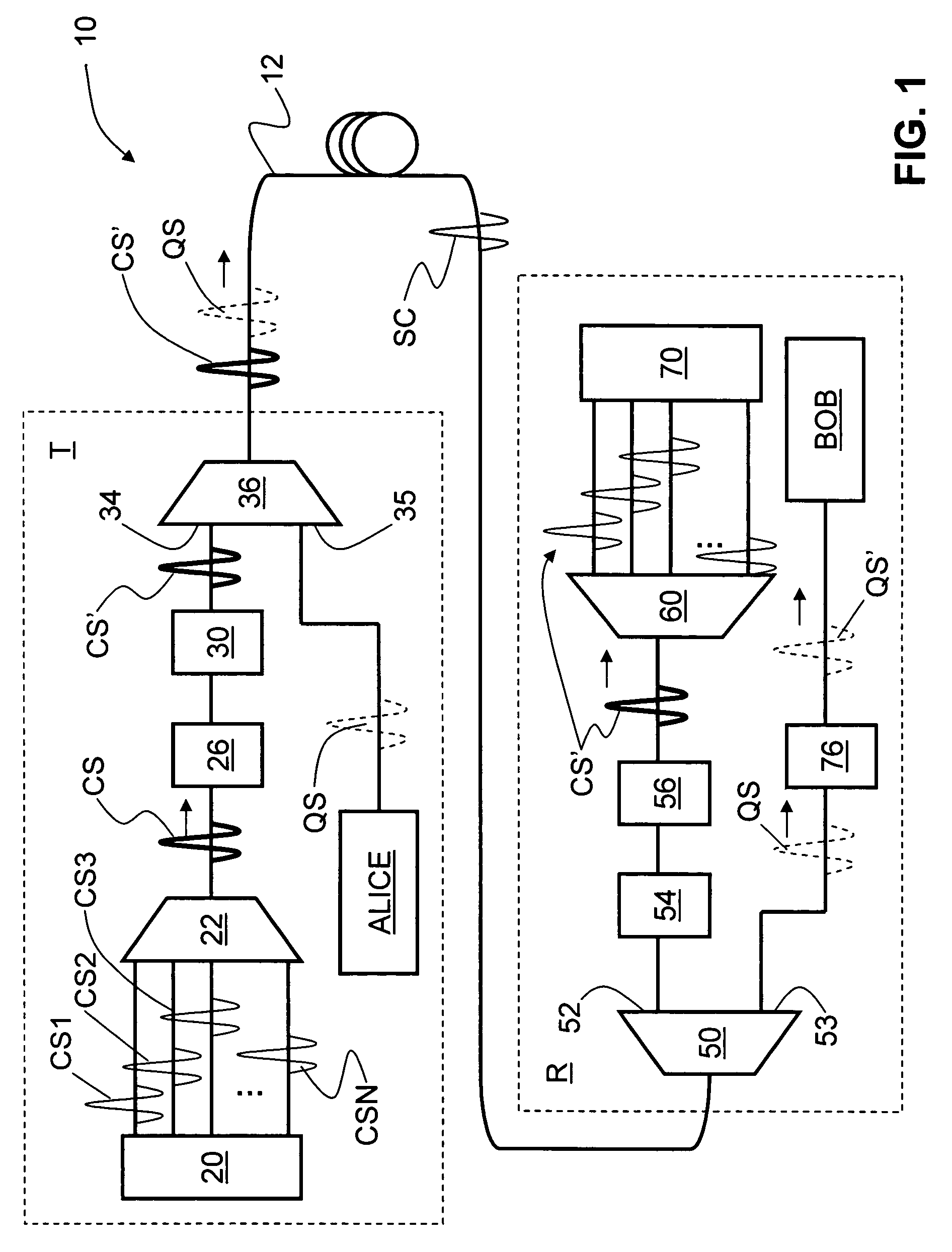
[0017]The present invention includes systems and methods that allow for the transmission of both quantum (optical) signals QS at quantum signal wavelength and high-speed classical (optical) signals CS at classical signal wavelength over an optical fiber network, wherein the quantum and classical signal wavelengths are relatively close to one another. In a preferred embodiment, the optical coupling between elements as referred to below is accomplished using sections of optical fiber.

[0018]FIG. 1 is a schematic diagram of an optical network 10 according to the present invention. Network 10 includes a transmitter side T and a receiver side R optically coupled by a transmission optical fiber 12. On receiver side R, network 10 includes a multi-wavelength transmitter 20 optically coupled to a dense wavelength division multiplexer (DWDM) 22, which in turn is optically coupled to an erbium-doped fiber amplifier (EDFA) 26. EDFA 26 is optically coupled to a “deep notch” optical filter 30 havi...


PUM


Abstract

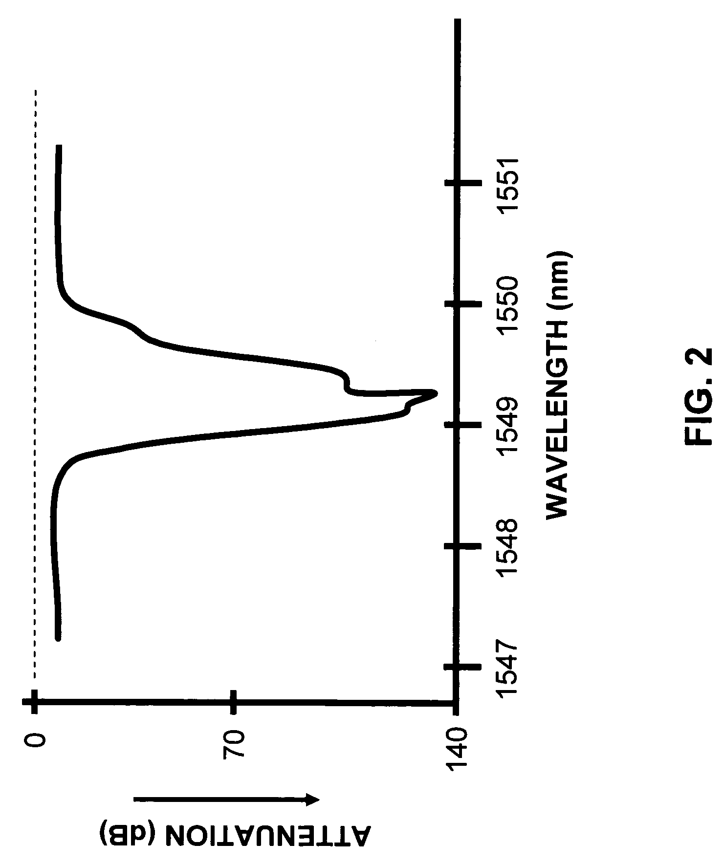
Systems and methods for transmitting quantum and classical signals over an optical network are disclosed, wherein the quantum signal wavelength either falls within the classical signal wavelength band, or is very close to one of the classical signal wavelengths. The system includes a deep-notch optical filter with a blocking bandwidth that includes the quantum signal wavelength but not any of the classical signal wavelengths. The deep-notch optical filtering is applied to the classical signals prior to their being multiplexed with the quantum signals to prevent noise generated by the classical signals from adversely affecting transmission of quantum signals in the transmission optical fiber. Narrow-band filtering is also applied to the quantum signals prior to their detection in order to substantially exclude spurious non-quantum-signal wavelengths that arise from non-linear effects in the optical fiber. The present invention allows for the quantum and classical signals to have wavelengths within just a few nanometers of one another, which has benefits for both classical and quantum signal transmission on a common transmission optical fiber.

Description

TECHNICAL FIELD OF THE INVENTION[0001]The present invention relates to optical networks and quantum cryptography, and in particular relates to transmitting quantum signals over an optical network populated by classical signals.BACKGROUND ART[0002]QKD involves establishing a key between a sender (“Alice”) and a receiver (“Bob”) by using either single-photons or weak (e.g., 0.1 photon on average) optical signals (pulses) called “qubits” or “quantum signals” transmitted over a “quantum channel.” Unlike classical cryptography whose security depends on computational impracticality, the security of quantum cryptography is based on the quantum mechanical principle that any measurement of a quantum system in an unknown state will modify its state. As a consequence, an eavesdropper (“Eve”) that attempts to intercept or otherwise measure the exchanged qubits will introduce errors that reveal her presence.[0003]The general principles of quantum cryptography were first set forth by Bennett and ...

Claims


Application Information

Patent Timeline
Patent Type & Authority Patents(United States)
IPC IPC(8): H04K1/00H04L9/00
CPCH04L9/0852
Inventor BEAL, A. CRAIGLAGASSE, MICHAEL J.
Owner MAGIQ TECH INC
Learn More