
Artificial eye system

a technology of artificial eye and eye, applied in the field of artificial eye system, can solve the problems of ineffective cure for blindness, not yet available, and have not yet been devised, and achieve the effects of reducing the power of output signal, excellent image signal, and induced

Inactive Publication Date: 2007-07-24
NIDEK CO LTD
View PDF16 Cites 33 Cited by
  • Summary
  • Abstract
  • Description
  • Claims
  • Application Information

AI Technical Summary

Benefits of technology

The present invention provides an artificial eye system that can be used to restore vision to blind patients. The system includes an extracorporeal unit and an intracorporeal unit, with the intracorporeal unit being mounted inside the user's body. The extracorporeal unit includes a visor and a power supply unit that supplies electricity to the visor. The intracorporeal unit includes a light receiving element and a signal processing circuit that processes the image signal received by the light receiving element. The system uses infrared light emitting diodes as the image signal and the image signal is transmitted to the retina through the pupil. The system is compact and can be designed to be easily integrated. The technical effects of the invention include improved usability, natural vision, and reduced power consumption.

Problems solved by technology

Despite the recent advancement in medical technologies, an effective cure for blindness has not been devised yet.
Something, which is movable with a user (blind patient) and has the image information transmission system and the power supply system combined appropriately, has not yet been available.

Method used


Image

  • Artificial eye system
  • Artificial eye system
  • Artificial eye system

Examples


Embodiment Construction

[0051]Next, embodiments of the present invention will be described below. The technological scope of the present invention is not limited to the embodiments. Various application of the invention can be implemented without departing from the scope of the invention. Moreover, the technological scope of the invention encompasses an equivalent scope.

[0052]Referring to FIG. 1 to FIG. 10, an embodiment of the present invention will be described below.

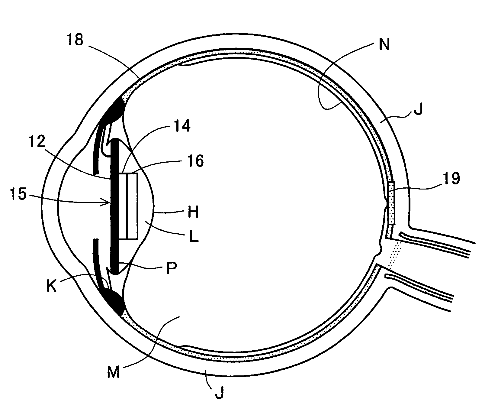
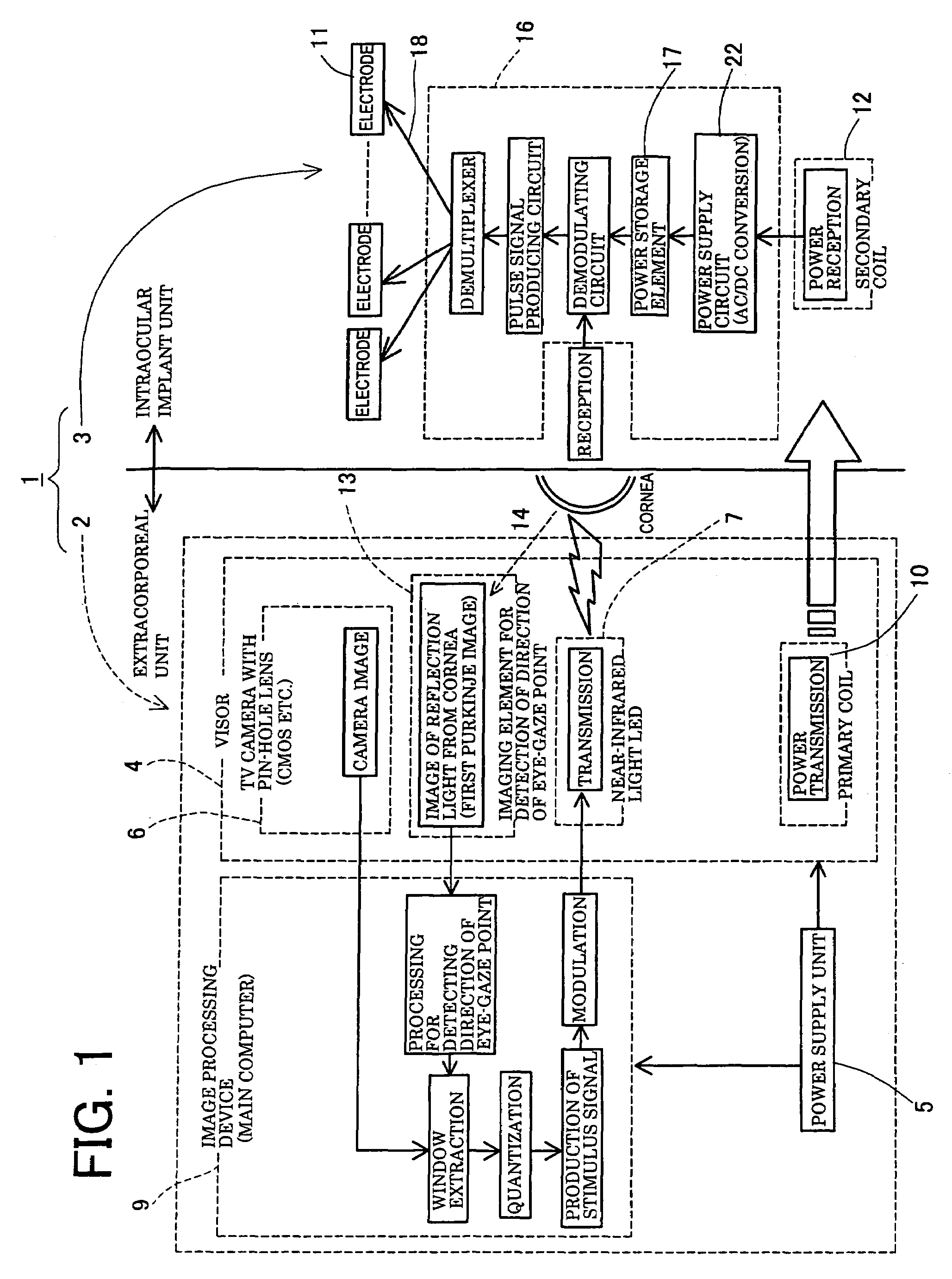
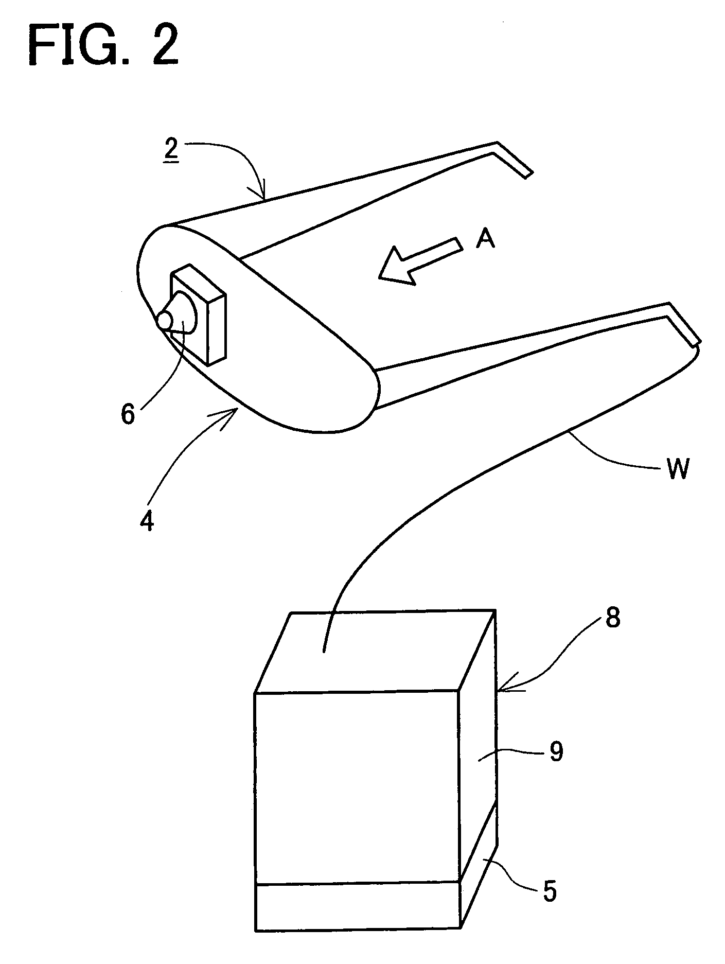
[0053]As shown in FIG. 1, an artificial eye system 1 in the present embodiment is constructed of an extracorporeal unit 2 which is mounted outside a user's body and an intracorporeal unit 3 which is mounted inside the user's body (specifically, in the eyeball).

[0054]The operation of the artificial eye system 1 will first briefly be explained below. A visor 4 included in the extracorporeal unit 2 has a TV camera 6 and eye-gaze point recognizing units 13. A signal component of a signal received by the TV camera 6 which represents information of...


PUM


Abstract

An artificial eye system may include an extracorporeal unit mounted outside a user's body and an intracorporeal unit 3 mounted inside a user's eye. The extracorporeal unit 2 may include a visor and a power supply unit. The visor may include a primary coil, an image receiving element that receives a picture image, a light emitting element that transmits an electric stimulus signal produced based on an image signal from the image receiving element, and an eye-gaze point recognizing unit. The intracorporeal unit may include a secondary coil that is electro-magnetically induced by the primary coil, a light receiving element that receives the electric stimulus signal from the light emitting element, a signal processing circuit that processes the electric stimulus signal received by the light receiving element, and a plurality of electrodes that transmits the electric stimulus signal processed by the signal processing circuit to the retina.

Description

TECHNICAL FIELD[0001]The present invention relates to an artificial eye system.BACKGROUND ART[0002]Despite the recent advancement in medical technologies, an effective cure for blindness has not been devised yet. Blindness is not limited to a mere loss of a visual function but is a disease seriously affecting the patient's mental life and social life. Therefore, technologies for curing blindness are acutely demanded.[0003]One of the blindness cure technologies is implemented in an artificial eye system designed to replace the function of a diseased part such as the retina or the optic nerve with an artificial entity. In general, the artificial eye system comprises an extracorporeal image receiving element and a nerve stimulating electrode implanted in an intracorporeal region. Image information received by the image receiving element is transmitted to the brain via the stimulating electrode. Therefore, at least an image information transmission system for transmitting the image info...

Claims


Application Information

Patent Timeline
Patent Type & Authority Patents(United States)
IPC IPC(8): A61N1/18A61F2/14A61F2/16A61F9/00A61F9/08
CPCA61F2/14A61F2/1602A61F9/0017A61F9/08A61N1/0543A61N1/36046A61F2/141
Inventor YAGI, TORU
Owner NIDEK CO LTD
Learn More