Electronic gas cooktop control with simmer system and method thereof

a technology of electric cooking and electric control, which is applied in the direction of combustion control, domestic stoves or ranges, combustion failure safe, etc., can solve the problems of difficult user, difficult to maintain, and difficult to achieve repeatability, and achieve the effect of facilitating the maintenance of such surfaces

Inactive Publication Date: 2007-08-14
COMPUVALVE +1
View PDF33 Cites 80 Cited by
  • Summary
  • Abstract
  • Description
  • Claims
  • Application Information

AI Technical Summary

Benefits of technology

[0009]A major object of the invention is a gas cooktop appliance capable of delivering very low heat power while maintaining capability of delivering very high BTU output, in each available burner, and also capable of fine, precise and repeatable control over the entire span of cooking levels. Another object of the present invention is to provide a gas cooktop appliance with an innovative electronic control featuring a capacitive touch user interface, thus featuring a flat, smooth and sealed cooking surface. Such a capacitive touch interface facilitates the maintenance of surfaces that are generally prone to become dirty and that are also difficult to reach. A capacitive touch interface offers the additional benefit of eliminating the wear and tear associated with mechanical devices and also of preventing contaminants such as greases and moisture from reaching sensitive components internal to the cooktop apparatus.
[0010]Another object is an electronic control capable of handling simultaneously both modulation of the valve(s) for metering the gas flow delivered to the burners from medium to high BTU output, and sequencing of the flame “on” and “off” at a predetermined medium level of flame, to provide efficient simmer temperatures. An additional object is to provide electronic control of a gas cooktop featuring a direct-dial keyboard-entry system and a digital visual user interface such that repeatability and precise re-selection of predetermined cooking levels is achieved. Yet another object is to provide an initial gas ignition and a flame sequencing re-ignition system that does not need to be synchronized with the flame on / off cycling during simmer cook mode and that does not generate harmful electromagnetic interference.SUMMARY OF THE INVENTION
[0012]Among features provided by this invention are: a capacitive touch keyboard interface, an entirely electronic control system controlling the gas flow through modulating valves; an innovative modulating valve activated through a pulse-width-modulation (PWM) port, capable of infinitely controlling the flow of gas while also providing for an “off” position, the electrical modulating valve therefore eliminating the need for an additional in-line solenoid valve to sequence the flame “on” and “off” during simmer operation; and ceramic hot-surface igniter(s) controlled and monitored by the electronic control system, capable of constant gas re-ignition without generation of electromagnetic interference.
[0013]Natural or propane gas is selectively provided to each individual burner, through the use of electrically actuated modulating valves, thus eliminating the need for mechanical valves and actuator knobs protruding through the user console and facilitating the maintenance of such surfaces. Ignition of the gas is monitored through temperature sensing, and ceramic hot-surface igniters are also monitored through current sensing. Safety features such as main in-line valve closure and de-energizing of the igniters are supported in the event that a fault condition occurs. Features such as visual and audible alarms are also generated, providing the user with positive indications of serious error conditions.

Problems solved by technology

While easily achieved in electric cooktops, simmer temperatures have until now been complicated issues for gas cooking apparatus.
With such knobs and associated infinite valves, it often becomes difficult for the user to precisely re-adjust the valve to a predetermined preferred level of BTU output and thus repeatability is rarely achieved.
Additionally, mechanical knobs are also usually susceptible to wear and tear and are often vulnerable to contaminants normally present in cooking areas, such as greases and moisture infiltration that generally find their way through open areas, necessary for the mechanical valve installation in the cooking surface.
However, very low flames have been proven hard to detect by such sensor types and are often a cause for spark igniters to unnecessarily generate discharges in response to false detection incidents.
Spark igniters are also known, by those in the industry, to emit powerful electromagnetic interference (EMI) that often disturbs electronic equipment working in their vicinity.
Microcontrollers used in electronic controls are also known to be highly susceptible to EMI emission, and hence generally need additional protection when used in conjunction with spark igniter modules in gas cooking apparatuses.
Due to their large orifice size, burners that are capable of high BTU output are usually not suitable for simmer, one of the reasons being that smaller flames have the tendency to self-extinguish in such conditions.
Moreover, repeated re-ignitions of the gas during simmer mode often have the undesirable effect of continuously generating harmful electromagnetic interference.
As mechanical valves are traditionally used to adjust the gas flow, additional electrically controlled “on / off” cycling solenoid valves are generally added to provide the “on / off” sequencing of the flame in simmer mode, contributing to higher system cost and reliability issues.

Method used


Image

  • Electronic gas cooktop control with simmer system and method thereof
  • Electronic gas cooktop control with simmer system and method thereof
  • Electronic gas cooktop control with simmer system and method thereof

Examples


Embodiment Construction

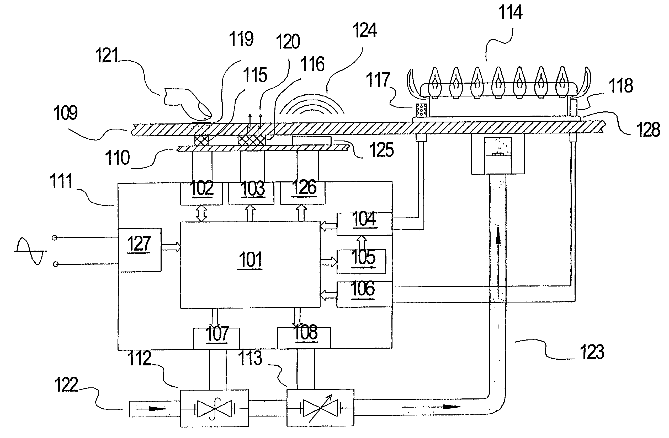
[0017]FIG. 1 is a basic block diagram of a cooktop system made in accordance with this invention. The cooktop shown in FIG. 1 has one or more gas burner(s) 114 placed on a ceramic glass panel 109; one electronically controlled in-line safety gas valve 112; one or more electronically controlled in-line modulating valve(s) 113; a gas line conduit 123 to conduct gas from the main gas supply to the burner(s) under control through the in-line valves; a user interface panel 110 preferably placed in registry with a silk-screened portion of a ceramic glass panel 109; one or more temperature sensor(s) 118; one or more hot-surface igniter(s) 117; and a controller 111 operative to control each of the gas valves in accordance with the user's selection entered at the user interface, the apparatus being controlled by a suitably programmed microcontroller 101.

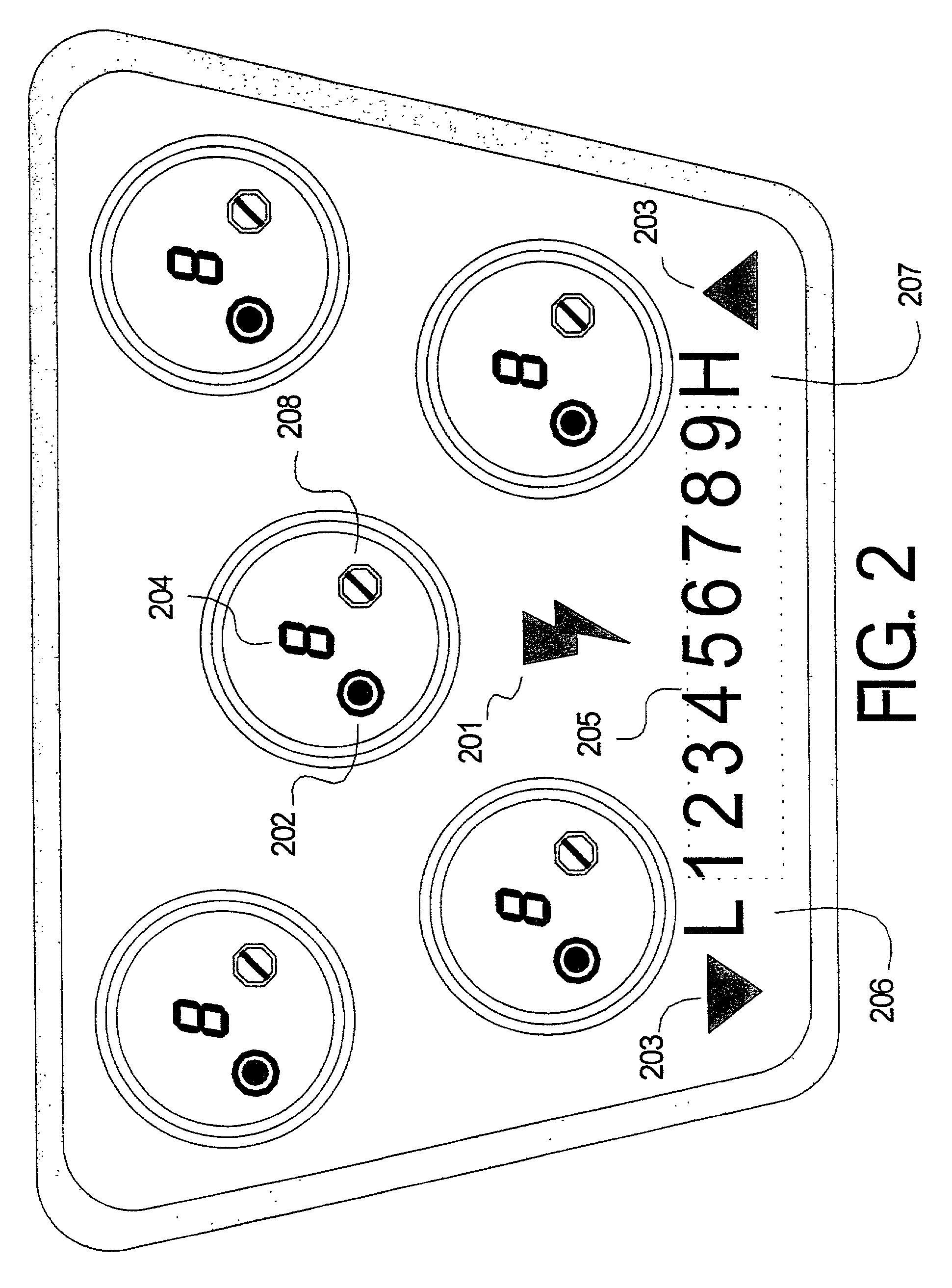
[0018]The user interface panel 110, placed in registry with a silk-screened portion of a ceramic glass panel 109, preferably further include...


PUM


Abstract

An electronically activated gas cooktop control system, responsive to a touch-sensitive user interface, and capable of providing a predetermined range of cooking and simmer levels of BTU output, has two complementary heating modes of operation A first heating mode of operation is provided to produce a wide selection of simmer levels of BTU output, by electronically sequencing a solenoid-operated modulating gas valve “on” and “off”, at a predetermined level of flame. A second cooking mode of operation is provided by electronically modulating the level of flame, through use of a pulse-width-modulation (PWM) output signal to produce a wide selection of cooking levels of BTU output. An igniter system capable of insuring proper ignition of gas without generating harmful electromagnetic interference is also provided.

Description

[0001]This application is a continuation of PCT application PCT / US00 / 28624, filed Oct. 16, 2000, which claims benefit of U.S. Provisional Patent Application 60 / 159,885, filed Oct. 18, 1999.TECHNICAL FIELD OF INVENTION[0002]This invention relates to control of gas appliances in general and more specifically to an electronically actuated gas cooktop flame proportioning control with flame sequencing simmer system.BACKGROUND ART[0003]While easily achieved in electric cooktops, simmer temperatures have until now been complicated issues for gas cooking apparatus. Conventional gas cooktops are generally operated by using manually activated mechanical actuator knobs, with infinitely varying settings of the flow of gas by rotating associated gas proportional valves. Most often, adjustment of cooking level is achieved by comparing level indicators printed on the knob, to a fixed pointer printed on the cooktop surface, immediately surrounding the knob. With such knobs and associated infinite v...

Claims


Application Information

Patent Timeline
Patent Type & Authority Patents(United States)
IPC IPC(8): F24C3/00F16K31/02F23N1/00F23N5/10F23N5/20F24C3/12
CPCF23N1/005F23N5/203F24C3/126F23N5/10F23N2027/10F23N2027/36F23N2027/42F23N2031/20F23N2031/22F23N2035/16F23N2037/02F23N2037/10F23N2041/08H03K2217/96066H03K2217/960785H03K17/9622F23N2227/10F23N2227/42F23N2231/22F23N2231/20F23N2227/36F23N2237/10F23N2241/08F23N2237/02F23N2235/16
Inventor REPPER, PIERRE P.SHUTE, ALAN B.SHUTE, CHRISTA B.SHUTE, SUZANNE J.OLSON, ALLEN L.ZHOU, FENG
Owner COMPUVALVE
Why Eureka
Try Eureka