Bonding structure and bonding method for cemented carbide element and diamond element, cutting tip and cutting element for drilling tool, and drilling tool

a cemented carbide element and diamond element technology, which is applied in the direction of drill bits, earthwork drilling and mining, natural mineral layered products, etc., can solve the problems of increasing the bonding strength between the cemented carbide element and the diamond element, increasing the bonding strength, and increasing the stress concentration in the diamond element with difficulty, so as to achieve advantageous bonding strength, easy to relieve, and increase the bonding strength

Active Publication Date: 2007-08-28
MITSUBISHI MATERIALS CORP
View PDF21 Cites 32 Cited by
  • Summary
  • Abstract
  • Description
  • Claims
  • Application Information

AI Technical Summary

Benefits of technology

[0010]According to this bonding structure, the cemented carbide element and the diamond element are bonded more strongly because the bonding layer includes the diffusion layer, and thereby the bonding strength between the cemented carbide element and the diamond element is increased, and separation becomes difficult. Moreover, applicability of the bonding structure of the present invention is not limited to drilling tools, and can be used in any field in which bonding between a diamond element and a cemented carbide element can be used.
[0030]An installation site is formed on the cutting base, where this installation site has a pair of support surfaces facing towards the leading edge in the drilling direction with a space opened therebetween. The diamond element can have a shape conforming to that of the installation site, and is attached therein. In this case, the diamond element can be supported by the pair of support surfaces, and thereby the impact applied to the diamond element can be relieved and the cutting force increased.

Problems solved by technology

According to this bonding structure, the cemented carbide element and the diamond element are bonded more strongly because the bonding layer includes the diffusion layer, and thereby the bonding strength between the cemented carbide element and the diamond element is increased, and separation becomes difficult.
Therefore, when returning to normal temperature and pressure after heat treatment during bonding, the stress that accumulates in the cemented carbide element and the diamond element is absorbed by this bonding layer, the stress concentrates in the diamond element with difficulty, and cracks or the like occur in the diamond element with difficulty.

Method used


Image

  • Bonding structure and bonding method for cemented carbide element and diamond element, cutting tip and cutting element for drilling tool, and drilling tool
  • Bonding structure and bonding method for cemented carbide element and diamond element, cutting tip and cutting element for drilling tool, and drilling tool
  • Bonding structure and bonding method for cemented carbide element and diamond element, cutting tip and cutting element for drilling tool, and drilling tool

Examples


examples

Experimental Example for Ni Diffusion

[0128]As a base material powder, a diamond powder having an average particle diameter of 10 μm and a purity of 99.9% or greater, and as a binding agent, a MgCO3 powder having an average particle diameter of 10 μm and a purity of 95% or greater were prepared.

[0129]The MgCO3 powder was made into a green compact having predetermined dimensions by press molding under a pressure of 100 MPa. Next, this green compact was charged into a capsule made of Ta, and the diamond powder was placed on the green compact to fill the capsule. The capsule was placed into a standard ultrahigh pressure belt sintering apparatus. A pressure of 7.7 GPa was applied to the capsule, a temperature of 2250° C. was maintained for 30 minutes, and ultrahigh pressure sintering was carried out to form a plurality of circular sintered diamond elements.

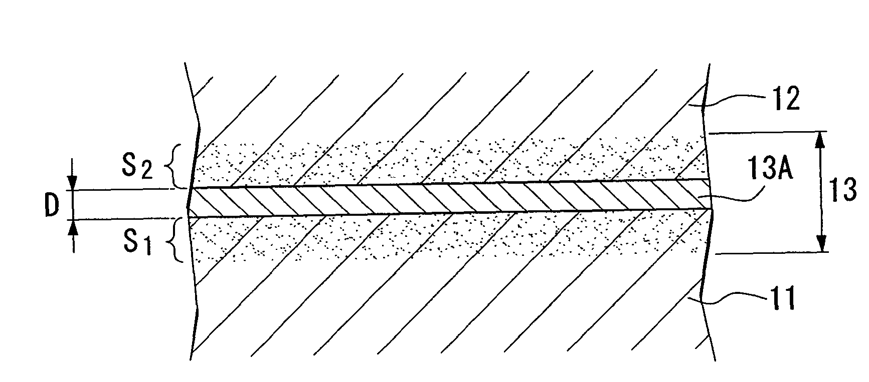
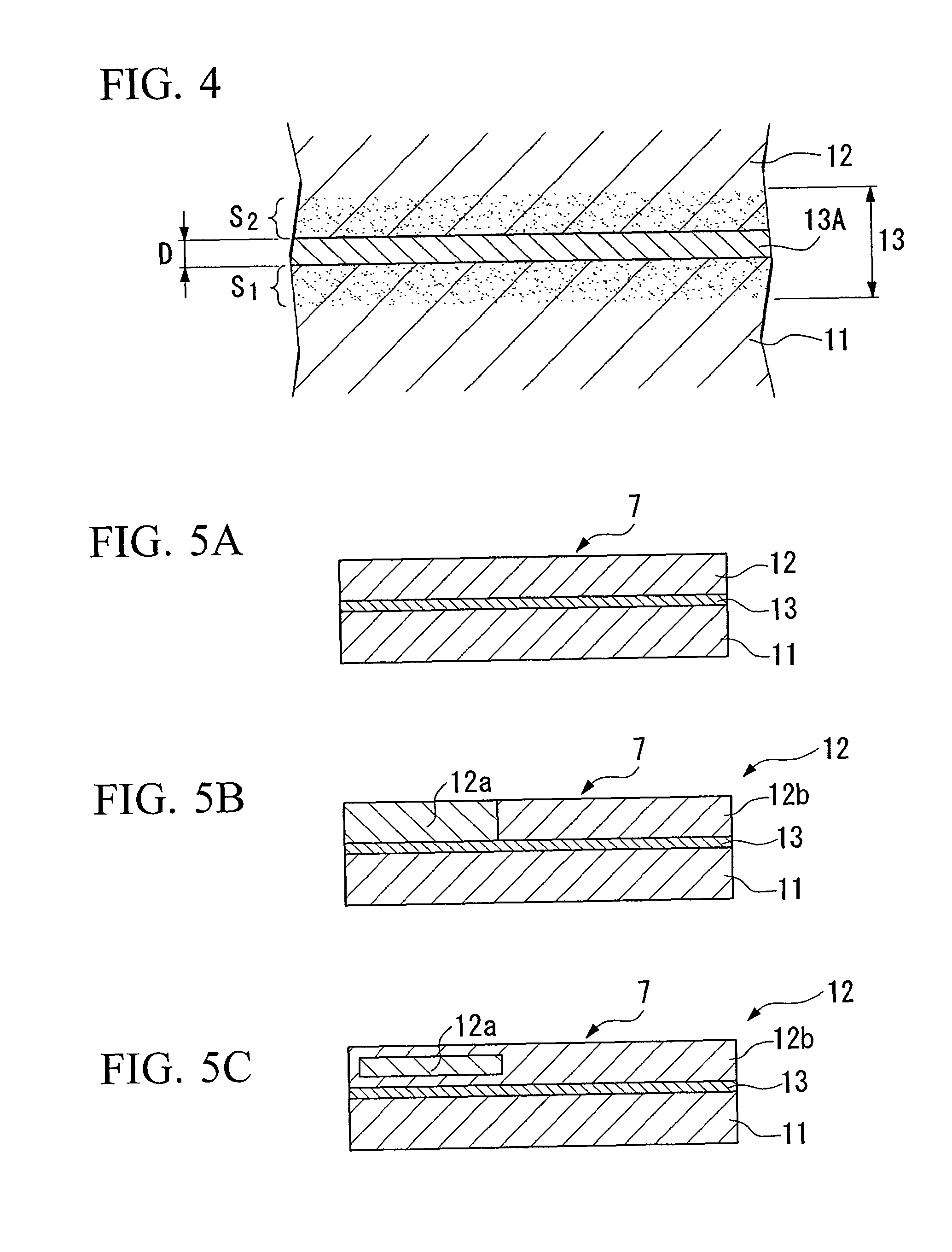
[0130]This diamond element had a diameter of 11 mm and a thickness of 1.5 mm, and includes MgCO3 at 4.0% by volume as a binding agent...


PUM

PropertyMeasurementUnit
melting pointaaaaaaaaaa
angleaaaaaaaaaa
angleaaaaaaaaaa

Abstract

A cutting tip for a drilling tool includes a cemented carbide cutting base 11, a diamond element 12 supported by the cutting base 11, and a bonding layer formed between the cutting base 11 and the diamond element 12 in order to bond them. The bonding layer 13 includes diffusion layers S1 and S2 in which one or two or more metals selected from a group consisting of Fe, Ni, Co, Ti, Zr, W, V, Nb, Ta, Cr, Mo, and Hf diffuses into at least one of the cemented carbide or the diamond.

Description

BACKGROUND OF THE INVENTION [0001]1. Field of the Invention[0002]The present invention relates to a bonding method and bonding structure between a cemented carbide element and a diamond element. In addition, the present invention relates to a cutting tip, cutting element, and a drilling tool for drilling a well (winze) or the like.[0003]2. Description of the Related Art[0004]Drilling tools are used to drill oil wells and other types of wells. As one such type of drilling tool, a drilling tool is known in which posts made of superhard tungsten carbide alloy (below, referred to as “cemented carbide posts”) are attached to the distal surface of an iron alloy tool body in a predetermined arrangement by methods such as brazing and shrinkage fitting, and cutting tips consisting of ultrahigh pressure sintered diamond (below, referred to as “sintered diamond”) are brazed to each of these cemented carbide posts. The drilling tool is mounted on the distal end of a pipe, the pipe is rotated wh...

Claims


Application Information

Patent Timeline
Patent Type & Authority Patents(United States)
IPC IPC(8): E21B10/46B23K35/30B22F7/06C04B35/645
CPCB22F7/06C04B35/52C04B35/5626C04B35/645C04B37/006C04B37/026Y10T407/27B23K35/3006B23K35/302B23K2201/002B23K2203/16B32B2311/30B32B2315/02C04B2235/3206C04B2235/3208C04B2235/3213C04B2235/3215C04B2235/3275C04B2235/3839C04B2235/405C04B2235/427C04B2235/442C04B2235/5436C04B2235/604C04B2235/6581C04B2235/80C04B2237/086C04B2237/122C04B2237/123C04B2237/124C04B2237/30C04B2237/36C04B2237/363C04B2237/40C04B2237/406B22F2998/00Y10T428/30Y10T407/25B22F2207/03B23K2101/002B23K2103/16B23K2103/172B23K35/30
Inventor YAMAMOTO, KAZUOOHASHI, TADAKAZUWARDOYO, AKHMADI EKO
Owner MITSUBISHI MATERIALS CORP
Why Eureka
Try Eureka