
Process for separating ti from a ti slurry

Inactive Publication Date: 2006-06-15
CRISTAL US INC
View PDF98 Cites 22 Cited by
  • Summary
  • Abstract
  • Description
  • Claims
  • Application Information

AI Technical Summary

Benefits of technology

[0008] Additional advantage, objects and novel feature of the invention will become apparent to those skilled in the art upon examination of the following and by practice of the invention.

Problems solved by technology

In developing the Armstrong Process with respect to titanium and its alloys, it has been found that the method of producing the slurry above referenced is very rapid and separation of the product from the slurry is the most difficult aspect in engineering of the continuous process.

Method used


Image

  • Process for separating ti from a ti slurry
  • Process for separating ti from a ti slurry
  • Process for separating ti from a ti slurry

Examples


Embodiment Construction

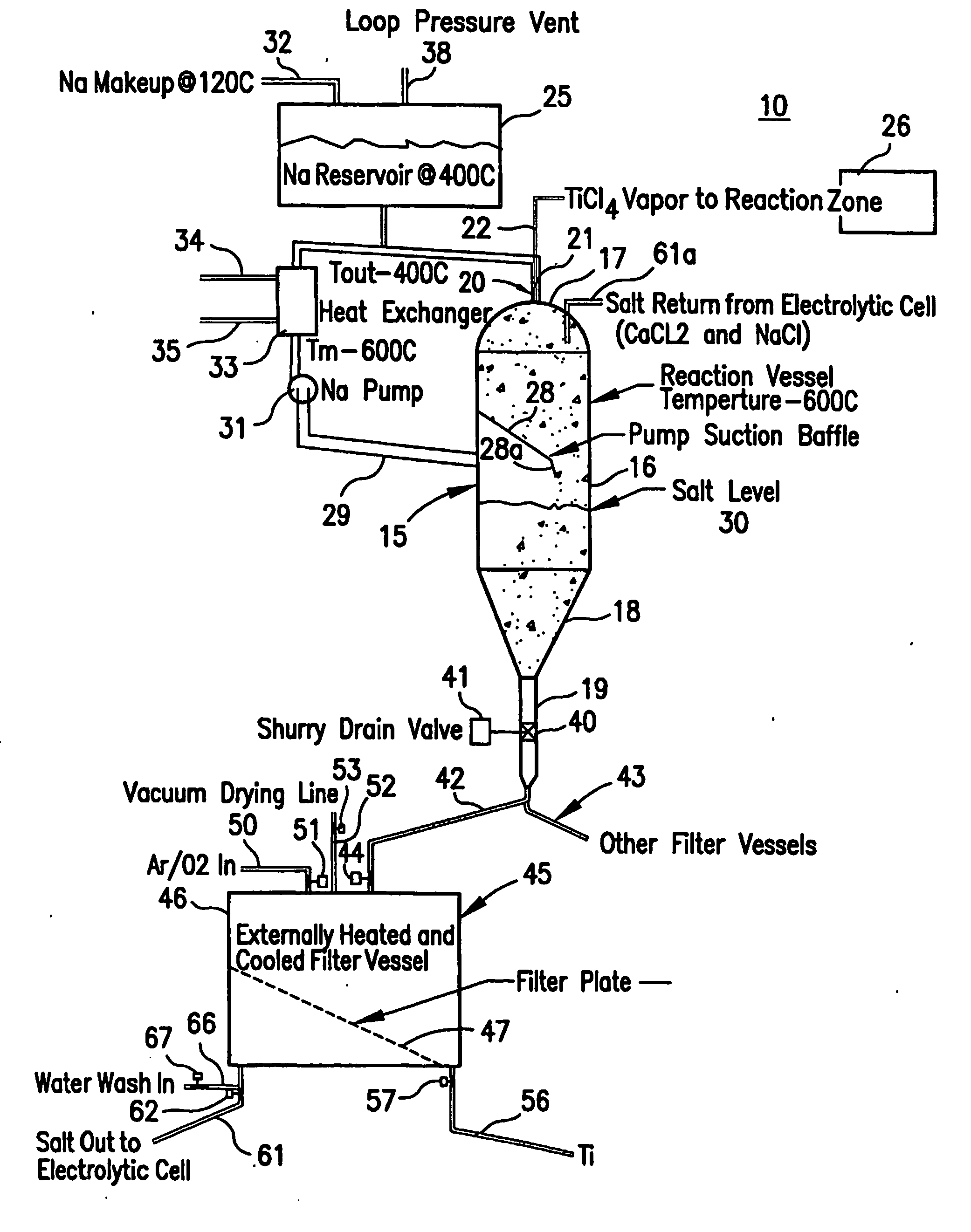
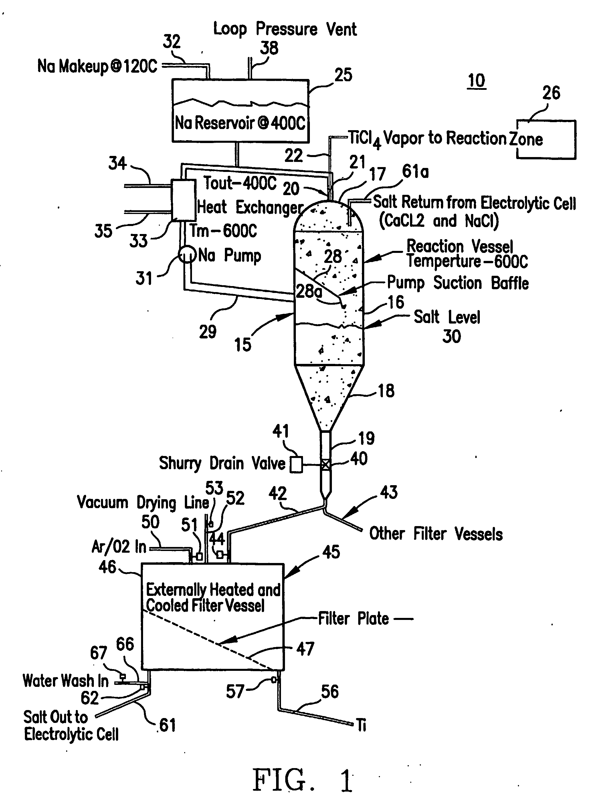
[0014] Referring now to the drawings and more particularly to FIG. 1, there is shown a separation system 10 in which a vessel 15 has a generally cylindrical portion 16 with a dome shaped top 17 and a frustoconical shaped bottom 18 and exit pipe 19 extending from the bottom of the vessel 15. A reactor 20 of the type disclosed in the above-referenced patents has a outer liquid metal or sodium tube 21 and an inner halide vapor or titanium tetrachloride tube 22. A liquid metal or sodium supply tank 25 feeds sodium to the sodium or other liquid metal to the reactor 20 and a halide boiler 26 feeds the appropriate halide vapor to the reactor 20, all as previously described.

[0015] Internally of the vessel 15 is a downwardly sloping baffle 28 having a distal end 28a extending at a more acute angle and generally opposite to a sodium or liquid metal outlet 29. The liquid metal outlet 29 is in fluid communication with a metal or sodium pump 31 which leads to a heat exchanger 33 having a fluid ...


PUM

PropertyMeasurementUnit
Temperatureaaaaaaaaaa
Fractionaaaaaaaaaa

Abstract

A method of separating metal particulates from a slurry of original constituents of liquid metal and metal particulates and salt particulates is disclosed. The metal and salt particulates are concentrated by removing at least some of the liquid metal, and then, liquid metal or a liquid of the original salt constituent or a mixture thereof is passed through the particulates at a temperature greater than the melting point of the original salt constituent to further concentrate the metal particulates. The metal particulates are then separated from the remaining original constituents or a mixture of the salt constituent. Density differences between the liquid metal and salt are also used to facilitate separation.

Description

RELATED APPLICATIONS [0001] This application, pursuant to 37 C.F.R. 1.78(c), claims priority based on provisional application Ser. No. 60 / 408,932, filed Sep. 7, 2002, U.S. Provisional Application Ser. No. 60 / 408,925, filed Sep. 7, 2002 and U.S. Provisional Application Ser. No. 60 / 408,933, filed Sep. 7, 2002BACKGROUND OF THE INVENTION [0002] This invention relates to the separation of unwanted constituents from a slurry produced during operation of the Armstrong Process and method to produce a product as disclosed in U.S. Pat. Nos. 5,779,761, 5,958,106 and 6,409,797 patents, the disclosures of which are herein incorporated by reference. As indicated in the above-identified and incorporated patents, the continuous process there disclosed, produces, for instance, titanium or a titanium alloy by the reduction of titanium tetrachloride with excess sodium. The product stream that exits the reactor is a slurry of liquid metal, salt particles or powder and titanium metal or metal alloy as p...

Claims


Application Information

Patent Timeline
IPC IPC(8): B22F9/04C22B5/04C22B34/12C22C14/00
CPCC22B9/023C22B34/1272C22B34/1231Y02P10/20
Inventor ANDERSON, RICHARD P.DONN, ARMSTRONGJACOBSEN, LANCE
Owner CRISTAL US INC
Learn More