
Sensor dispensing device

Active Publication Date: 2007-09-04
ARKRAY INC
View PDF181 Cites 162 Cited by
  • Summary
  • Abstract
  • Description
  • Claims
  • Application Information

AI Technical Summary

Benefits of technology

[0020]By providing the sealing means on the cartridge, problems of wear are reduced because the seals are replenished each time the cartridge is replaced.
[0021]In a preferred embodiment each of the sealing means comprises a tube of a natural or synthetic rubber material. Suitable materials include styrene-ethylene-butylene-styrene (SEBS), for example Thermoflex™, ethylene-propylene-diene monomer (EPDM) terpolymer, optionally alloyed with other materials such as polypropylene. Preferred materials are thermoplastic elastomers, for example Santoprene™, a nitrile rubber mixed with polypropylene, or thermoplastic polyurethane elastomers, for example Pellethane™. A preferred material is a mixture of Thermoflex™ 45A with Nourymix™ SP E60 antistatic / slip agent (from Akzo Nobel Chemicals). Nourymix™ SP E60 comprises 80% of a rapeseed oil-based erucamide (13-docosenamide) on a polypropylene carrier. The additive helps to prevent sticking of the tubular elastomer after being clamped for a length of time. The concentration of Nourymix™ is preferably in the range 0.2 to 5%, notably about 3%. Each tube may be disposed through its associated aperture and be a close fit for this aperture. Thus, when the tubes are suitably clamped or nipped the inside of the cartridge is sealed from moisture.
[0024]The pusher is preferably flexible so that it can be coiled on a drum or other suitable support so that the device may be made compact. A running guide may be incorporated into the cartridge mouldings so that the pusher will be supported throughout its travel through the cartridge to facilitate reliable dispensing of a thin test strip. Provision of a guiding slot creates the potential for the pusher to be moulded as a single component, for example of acetal.

Problems solved by technology

A problem with test strips is that they have only a limited shelf life, and exposure of test strips to the atmosphere further reduces the shelf life.
A problem with such systems is that the sealing means may wear with repeated use and the quality of the seal may consequently be reduced.
Such an arrangement is less desirable for test members in which the reagents are not located in an opening of a moisture-impermeable slide member because it is difficult to make a reliable seal around the reagents.
Friction between the reagent layer and the plate may also tend to abrade the reagent layer.

Method used


Image

  • Sensor dispensing device
  • Sensor dispensing device
  • Sensor dispensing device

Examples


Embodiment Construction

[0047]In the embodiments illustrated in the drawings, parts which perform the same function will be denoted by the same numbers.

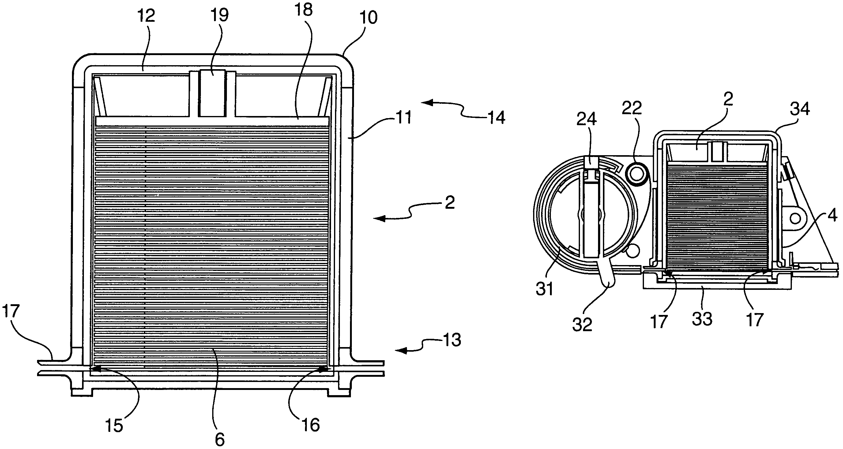
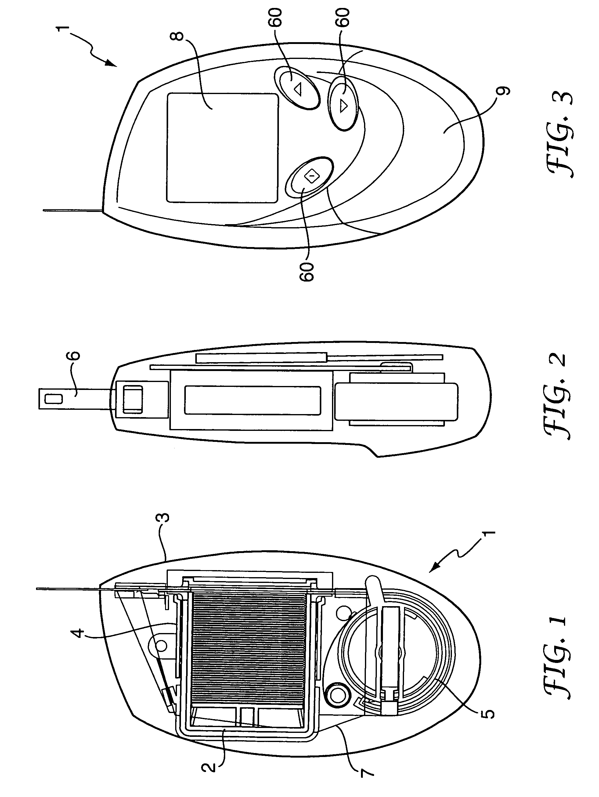
[0048]The blood glucose meter 1 shown in FIGS. 1 to 3 comprises an outer casing 3 which houses a cartridge 2 and a delivery mechanism 5 for dispensing test strips 6 from the cartridge 2. The casing 3 also houses a moveable clamp 4 for sealing the inside of the cartridge 2 from atmospheric moisture, as will be described in more detail below. The external features of the meter 1 comprise control buttons 60 for controlling the operation of the meter, an LCD 8 for displaying user instructions, results and other data, and an external handle 9 for actuating the delivery mechanism. A control PCB 7 is operably connected to the LCD 8 and buttons 60. The meter 1 of FIGS. 1-3 is shown with a test strip 6 in a dispensed position ready to receive a drop of blood.

[0049]Referring now to FIGS. 4 and 5, the cartridge 2 has an inner assembly 12 and an outer casing 11, in thi...


PUM


Abstract

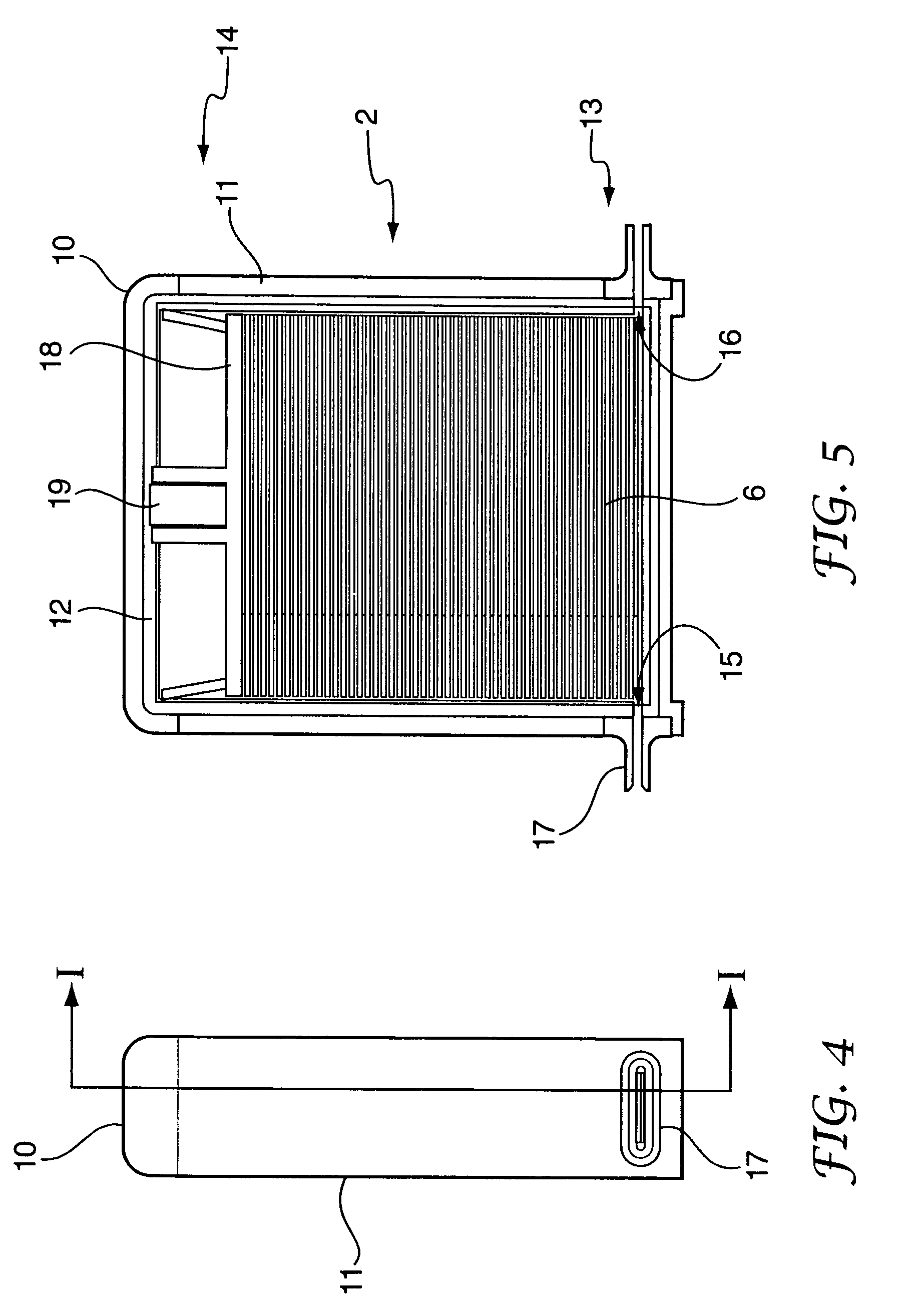
A sensor dispensing device (1) comprises a cartridge (2) having an outer casing (11) and a plurality of sensors (6) arranged one upon another in a stack. The cartridge has a first dispensing end (13) and a second opposing end (14) spaced a fixed distance apart, and the cartridge includes a first aperture (15) for the ejection of a sensor closest to the first end and a second aperture (16) opposed to the first aperture, for access by a pushing member (25). The first aperture and the second aperture are each provided with compliant sealing means (17) which are at least partly disposed outside the outer casing. The sealing means have first and second sealing surfaces which are capable of co-operating to releasably form a substantially moisture-tight seal when acted upon by suitable clamping forces. The device has a housing (34) for receiving the cartridge. For each of the compliant sealing means (17) there is a pair of clamping members (4, 33) for releasably clamping the sealing means to form a substantially moisture-tight seal. The device has a pushing member (25) for reversible insertion through the second aperture when the sealing means are not clamped, for pushing the sensor closest to the first end through the first aperture to a dispensed position.

Description

[0001]This application claims priority to now abandoned U.S. provisional application Ser. No. 60 / 441,503 filed on Jan. 21 2003, which is entitled “SENSOR DISPENSING DEVICE” the disclosure of which is incorporated herein by reference. This application also claims priority to United Kingdom patent application serial number 0300765.5 filed Jan. 14, 2003, which is entitled “SENSOR DISPENSING DEVICE” the disclosure of which is also incorporated herein by reference.BACKGROUND OF THE INVENTION[0002]1. Field of the Invention[0003]The present invention relates to a device for dispensing sensors for measuring the concentration of an analyte in a fluid sample (notably glucose in whole blood), and to a cartridge containing sensors for use in the device. The invention also provides a meter incorporating the dispensing device.[0004]2. Description of the Prior Art[0005]Diabetics regularly need to test samples of their blood to determine the levels of blood glucose. In one known type of test system...

Claims


Application Information

Patent Timeline
IPC IPC(8): B65H59/02G01N33/487
CPCG01N33/48757
Inventor BRICKWOOD, DAVIDMAISEY, GRAEMEMAY, STUART RICHARD
Owner ARKRAY INC
Learn More