
Rare earth silicate single crystal and process for production of rare earth silicate single crystals

a technology of rare earth silicate and single crystal, which is applied in the direction of instruments, silicon compounds, under a protective fluid, etc., can solve the problems of crystal fracture and fracture (cleavage fracture) that have occurred, and achieve the effect of reducing crystallinity and adequately preventing the generation of cleavage fractur

Active Publication Date: 2007-09-04
OXIDE
View PDF6 Cites 4 Cited by
  • Summary
  • Abstract
  • Description
  • Claims
  • Application Information

AI Technical Summary

Benefits of technology

"The present invention provides rare earth silicate single crystals that can prevent cleavage fracture even at large sizes, and a process for their production. The problem of fracture has been observed during the production of rare earth silicate single crystals, particularly large ones, and is caused by thermal stress, residual stress, and internal crystal defects. The invention proposes a solution by creating a crystal face composed of multiple smooth partial region surfaces, each with an area detectable by X-ray diffraction, and meeting the condition of inequality (1). The invention also provides a single crystal where the cleavage plane orientations are not uniform, which further prevents fracture. The rare earth silicate single crystals produced using this process have been found to have adequate crystal quality for optical materials such as scintillators."

Problems solved by technology

However, when GSO single crystals are produced by the conventional melt process, fracture (cleavage fracture) has occured during the single crystal growth step, the cutting step for cutting the obtained single crystals (or single crystal ingots), or the polishing step for polishing the single crystals (or single crystal ingots).
For example, in the case of GSO single crystals, since cleavage can be formed along the (100) plane and the thermal expansion coefficient in the [010] axis direction is 2-3 times the thermal expansion coefficient in another axis direction, this has been a cause of crystal fracture.
This problem has also occurred with single crystals made of inorganic materials other than GSO single crystals.

Method used


Image

  • Rare earth silicate single crystal and process for production of rare earth silicate single crystals
  • Rare earth silicate single crystal and process for production of rare earth silicate single crystals
  • Rare earth silicate single crystal and process for production of rare earth silicate single crystals

Examples


example 1

[0087]A mixture of 20489.1 g of Gd2O3, 97.8 g of CeO2 and 3413.1 g of SiO2 (total of 24,000 g) was loaded into an Ir crucible with a 180 mm diameter, a 180 mm height and a 3 mm thickness. The mixture was then heated in a high-frequency induction heating furnace to above 1950° C. and melted down to obtain a molten liquid comprising Ce0.01Gd1.99SiO5.

[0088]Next, the tip of a lifting rod having a seed crystal fixed to its lower end was introduced into the molten liquid for seeding. A single crystal ingot with an 8 mm neck diameter was lifted out at a lifting speed of 1-3 mm / h to form a neck section. A cone section (cylindrical section) was then lifted out, with lifting of the cylindrical section starting when the diameter (D) reached 105 mm. After growing the cylindrical section, the single crystal ingot was cut away from the molten liquid and cooling was initiated.

[0089]In order to simultaneously satisfy the conditions of inequalities (10) and (11) above, the cooling time A was 30 hour...


PUM

PropertyMeasurementUnit
diameteraaaaaaaaaa
volumeaaaaaaaaaa
anglesaaaaaaaaaa

Abstract

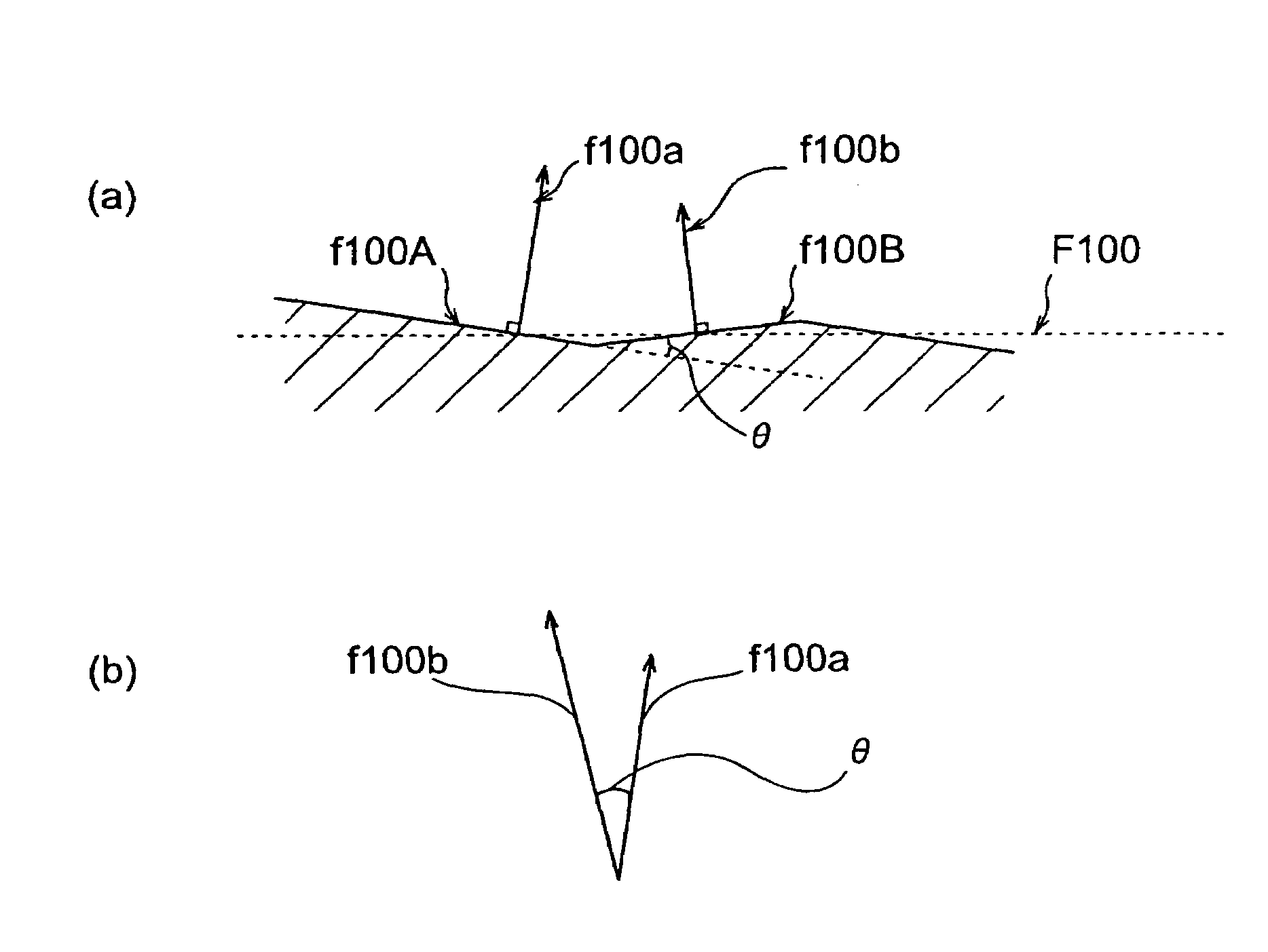
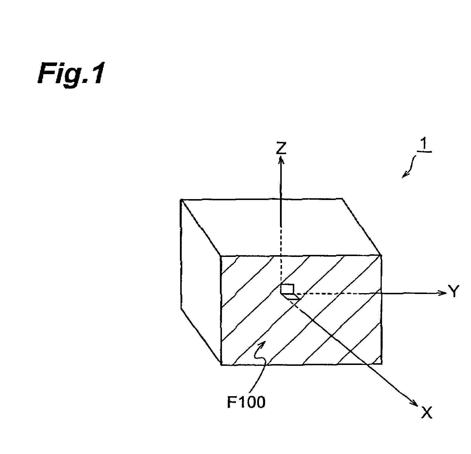
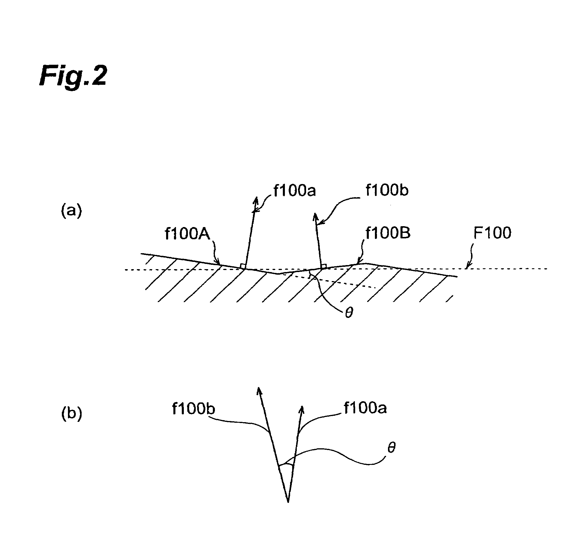
When produced as a single crystal ingot, a rare earth silicate single crystal 1 can be formed by cutting out from the single crystal ingot. The single crystal 1 has a crystal face F100 whose Miller indices can be determined by X-ray diffraction. The crystal face F100 is composed of a plurality of smooth partial region surfaces (for example, the partial region surface f100A and partial region surface f100B), the plurality of partial region surfaces each have an area detectable by X-ray diffraction, and the angles θ formed between the normal vectors of the plurality of partial region surfaces satisfy the following inequality:0.1°≦θ≦2.0°.  (1)

Description

[0001]This application claims priority from Japanese Patent Application No. P2004-180161, filed Jun. 17, 2004 and Japanese Patent Application No. P2003-279335, filed Jul. 24, 2003, the entire disclosures of which is incorporated herein by reference.BACKGROUND OF THE INVENTION[0002]1. Field of the Invention[0003]The present invention relates to rare earth silicate single crystals used for scintillators and the like, as well as to a process for production of the rare earth silicate single crystals.[0004]2. Related Background Art[0005]A “melt process”, whereby single crystals are produced from molten liquid obtained by heating starting material, is known as a process for production of single crystals used in electronic devices and the like, such as Ce-added Gd2SiO5 single crystals (hereinafter referred to as “Gd2SiO5:Ce single crystals” or “GSO single crystals”, as necessary) used as scintillator materials (for example, Japanese Patent Laid-Open No. 3-103398 and Japanese Patent Laid-Op...

Claims


Application Information

Patent Timeline
Patent Type & Authority Patents(United States)
IPC IPC(8): C30B29/34C30B1/00C30B15/00C30B15/14C30B23/00C30B25/00C30B28/12C30B28/14C30B33/00
CPCC30B29/34C30B33/00
Inventor KURASHIGE, KAZUHISASHIMURA, NAOAKIISHIBASHI, HIROYUKIGUNJI, AKIHIROKAMADA, MITSUSHI
Owner OXIDE
Learn More