Engine starting and stopping control device

a control device and engine technology, applied in the direction of engine starters, electric control, instruments, etc., can solve the problems of affecting the starting speed of the engine, the driver is likely to feel slowness, and the starting sound of the starter becomes a jarring nois

Inactive Publication Date: 2007-09-11
DENSO CORP
View PDF8 Cites 40 Cited by
  • Summary
  • Abstract
  • Description
  • Claims
  • Application Information

AI Technical Summary

Benefits of technology

[0008]The present invention is accomplished in view of the above-mentioned circumstances, and aims to provide an engine stopping and starting control device that can complete the starting in a short period without deteriorating the exhaust emission.
[0010]In an intake port injection engine, for example, fuel is injected to the cylinder that is predicted by the prediction means during the intake stroke immediately before the stop, whereby the engine is stopped with the air-fuel mixture sucked into and sealed in the cylinder. Further, in the direct fuel injection engine, fuel is injected to the cylinder, which is predicted by the prediction means during the intake stroke immediately before the stop or at the compression stroke, whereby the engine is stopped with the air-fuel mixture sealed in the cylinder. This defines a state wherein the air-fuel mixture is already sealed in the cylinder that is on the compression stroke of the next starting operation, thereby being capable of generating a first explosion by firing this cylinder on the compression stroke. According to this, the first explosion can be generated in a short period of within one stroke from the start of the cranking, so that the starting can be completed in a short period. Further, different from the injection asynchronous with the starter, fuel is not injected to the cylinder that is not used for the starting operation combustion. Thus, there is no chance to deteriorate the exhaust emission during the starting operation.
[0014]As a countermeasure, the engine stopping position is controlled to be the point before the passage of the predetermined crank angle for securing the combustion pressure for the first explosion at the next starting, i.e., to be the position where the compression pressure of the air-fuel mixture in the cylinder on the compression stroke is low (the position where the rising amount of the piston to the top dead center can be secured at the next starting). This reduces the leakage of the air-fuel mixture in the cylinder on the compression stroke or reduction in the compression pressure upon the engine stop. Further, the air-fuel mixture in the cylinder on the compression stroke can sufficiently be compressed for the next starting operation, thereby surely generating the first explosion having sufficient combustion pressure and, hence, one compression starting can surely be realized.
[0015]According to another aspect of the present invention, upon predicting which cylinder is on the compression stroke upon the stop, a motion parameter representing the motion of the engine and a hindering parameter hindering the motion of the engine are calculated during the process for stopping the engine. A future parameter representing the future motion of the engine is predicted based on the above two parameters and the cylinder that is on the compression stroke upon the stop is predicted based on the predicted value of the future parameter. This can precisely predict the future parameter by considering a dispersion due to a manufacturing tolerance of the engine, secular change, and change in the engine friction (for example, difference in viscosity due to oil temperature change of the engine oil), during a process for calculating the motion parameter and the hindering parameter, with the result that the cylinder that is on the compression stroke upon the engine stop can be precisely predicted from the future parameter.
[0017]Moreover, in another aspect of the present invention, upon controlling the engine stopping position, the intake air amount is increased when the cylinder that is predicted to be stopped on the compression stroke by the prediction means is in the intake stroke immediately before the engine stop, whereby the compression pressure of the cylinder on the compression stroke upon the stop is increased to stop the revolution of the engine. When the compression pressure in the compression stroke is increased when the revolution of the engine is stopped as described above, the negative rotational torque generating in the compression stroke is increased to act as a force for hindering the revolution of the engine. This results in a brake force that is applied on the revolution of the engine and the crank angle range in which the rotational torque becomes not more than the engine friction (the crank angle range in which the revolution of the engine can be stopped) is narrowed, and hence, the revolution of the engine is stopped within this crank angle range. This makes it possible to control the engine stopping position to be the point after the intake valve of the cylinder on the compression stroke upon the stop is closed and before the predetermined crank angle that can secure the combustion pressure for the first explosion. Moreover, the engine stopping position can be controlled by utilizing means for controlling the intake air amount (e.g., idle speed control valve, electronic throttle valve, variable valve mechanism) so that the present invention can be applied to the existing engine control system only by changing the control program.
[0018]The aspects of the invention explained above can be applied to the case where a driver operates an ignition switch to stop and start the engine, but the present invention may be applied to an idle stop system provided with automatic stop means for stopping the fuel injection and ignition to stop the revolution of the engine when a predetermined automatic stop condition is established during the idling, wherein the cylinder on the compression stroke upon the stop is predicted to inject the fuel to thereby seal the air-fuel mixture in the cylinder at the engine stop (idling) by the automatic stop means, and when the predetermined automatic start condition is established, the starting control is started to fire the cylinder on the compression stroke upon the stop, thereby generating the first explosion to restart the engine. This enables to realize one compression starting that cannot be realized by the conventional idle stop system, whereby the demand for shortening the starting time can be satisfied and the feeling of slowness at the restart is not recognized by a driver. Further, the noise due to the driving sound of the starter can be reduced, thereby satisfying the demand for silence.

Problems solved by technology

Therefore, taking a four-cylinder engine as an example, two to three strokes are required from the start of the cranking to the first explosion, thereby entailing a disadvantage that the starting time increases by that much.
When the starting time increases in a vehicle having mounted thereto an idle stop system wherein the engine is automatically stopped (idle stop) when a predetermined automatic stop condition is established during the idling and the engine is automatically restarted by an operation on an accelerator pedal by a driver, in particular, the driver is likely to feel slowness upon the restart or the driving sound of the starter becomes a jarring noise, so that the demand for shortening the starting time is strong.
However, both starting methods described above require a process in which fuel is injected and sucked into the cylinder performing the intake stroke after the start of the cranking.
Therefore, a period of almost two strokes is required from the start of the cranking to the first explosion, with the result that the required starting time cannot be satisfied in the case of restarting after the idle stop.
Additionally, in the injection system asynchronous disclosed in Japanese patent document JP-1-170735A, fuel is injected to all cylinders at the beginning of the starting operation so that the fuel not used for the combustion is emitted intact, thereby entailing a problem of deteriorating the exhaust emission during the starting operation.

Method used


Image

  • Engine starting and stopping control device
  • Engine starting and stopping control device
  • Engine starting and stopping control device

Examples


Embodiment Construction

[0031]Explained hereinafter is one embodiment of the present invention, wherein the best mode for carrying out the present invention is embodied by an intake port injection type four-cylinder engine.

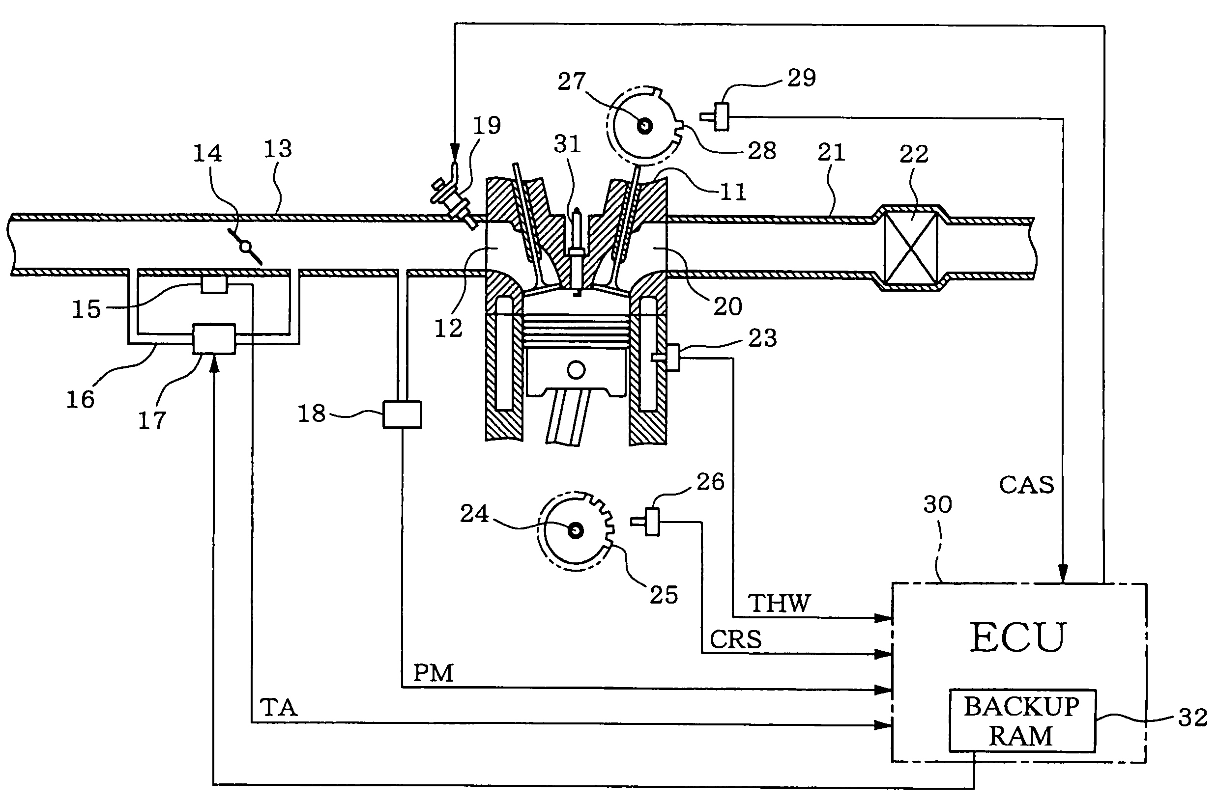
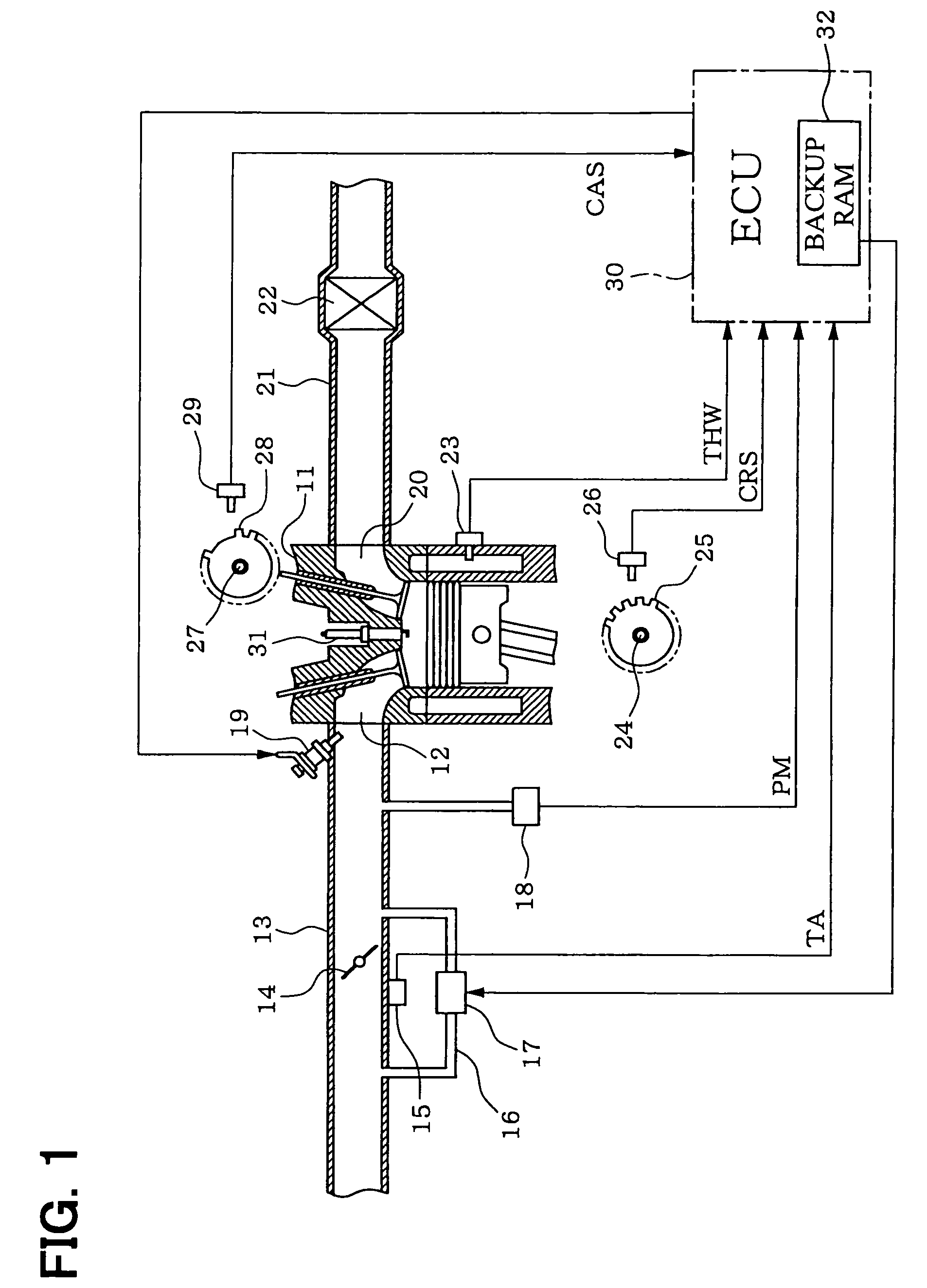
[0032]Firstly, an entire configuration of an engine control system will be explained with reference to FIG. 1. A throttle valve 14 is mounted to an intake pipe 13 connected to an intake port 12 of an engine 11. An opening of this throttle valve 14 (throttle opening) TA is detected by a throttle opening sensor 15. A bypass path 16 is mounted to the intake pipe 13 for bypassing the throttle valve 14. An idle speed control valve (hereinafter referred to as “ISC valve”) 17 is mounted to this bypass path 16. An intake manifold pressure sensor 18 for detecting an intake manifold pressure PM is mounted at the downstream side of the throttle valve 14 and a fuel injection valve 19 is attached in the vicinity of the intake port 12 of each cylinder.

[0033]A catalyst 22 for purifying exhaust gas is m...


PUM


Abstract

An engine stopping and starting control device predicts which cylinder will be on a compression stroke upon being stopped during a process for stopping the engine. Fuel is injected into the predicted cylinder during the process for stopping the engine to seal an air-fuel mixture therein. The same cylinder is then fired upon the next start cycle to generate a first explosion to start the engine.

Description

CROSS REFERENCE TO RELATED APPLICATIONS[0001]This application is based upon and claims the benefit of priority of Japanese Patent Application No. 2004-114439, filed on Apr. 8, 2004, the contents of which are incorporated herein by reference.FIELD OF THE INVENTION[0002]The present invention relates to an engine starting and stopping control device having enhanced startability.BACKGROUND OF THE INVENTION[0003]Generally, a cylinder is determined based on an output signal from a crank angle sensor and a cam angle sensor and a crank angle is detected to perform an ignition control or fuel injection control when the engine is being operated. Therefore, the first firing and injecting cylinder is unclear until the engine is cranked by a starter to complete the determination of the cylinder. Accordingly, upon the start of the engine, the fuel injection is performed to a cylinder that can combust the fuel as fast as possible and ignition is performed to generate a first explosion to start the...

Claims


Application Information

Patent Timeline
Patent Type & Authority Patents(United States)
IPC IPC(8): F02D45/00F02D15/00F02P9/00F02D17/00F02D29/02F02D41/04F02D41/06F02D43/00F02N9/02F02N11/08F02N15/00F02N99/00
CPCF02D41/042F02D41/065F02N11/0814F02D2041/1415F02D2041/1416F02N19/005F02N99/006F02N2019/008Y02T10/48Y02T10/40
Inventor MURAKAMI, YOSHIFUMINISHIKAWA, SEIICHIROU
Owner DENSO CORP
Why Eureka
Try Eureka