Thermal pulsed ultrasonic flow sensor

Inactive Publication Date: 2007-09-18
ONICON INC
View PDF7 Cites 67 Cited by
  • Summary
  • Abstract
  • Description
  • Claims
  • Application Information

AI Technical Summary

Benefits of technology

[0008]In yet another preferred embodiment of the invention having two receiving transducers arranged side by side along the path of fluid flow, both receiving elements are preferably equally exposed to acoustic transmissions from a single transmitting transducer and used to differentially detect the passage of the bolus. This detection method is more sensitive to the effects of small acoustic differences and more tolerant of environmental variations which may otherwise produce flow rate measurement error.
[0009]Because a portion of the flowing fluid is heated by the flow meter, the power requirements for operating such a meter can limit its practical size if it is to sense flow rate across the entire cross section of the f

Problems solved by technology

The relatively long time required for temperature sensors to respond to the fluid temperature rise relegates this method to measurement of low fluid flow rates.
In addition, the temperature sensor elements

Method used


Image

  • Thermal pulsed ultrasonic flow sensor
  • Thermal pulsed ultrasonic flow sensor
  • Thermal pulsed ultrasonic flow sensor

Examples


Embodiment Construction

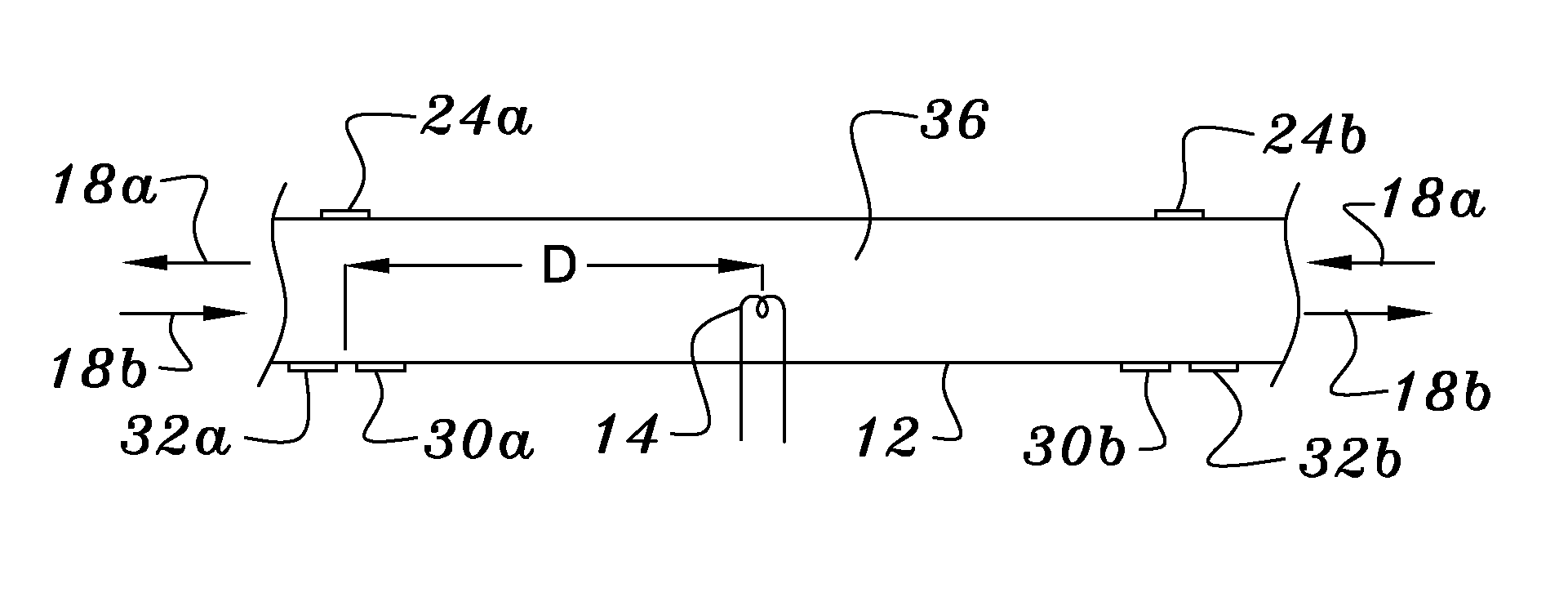
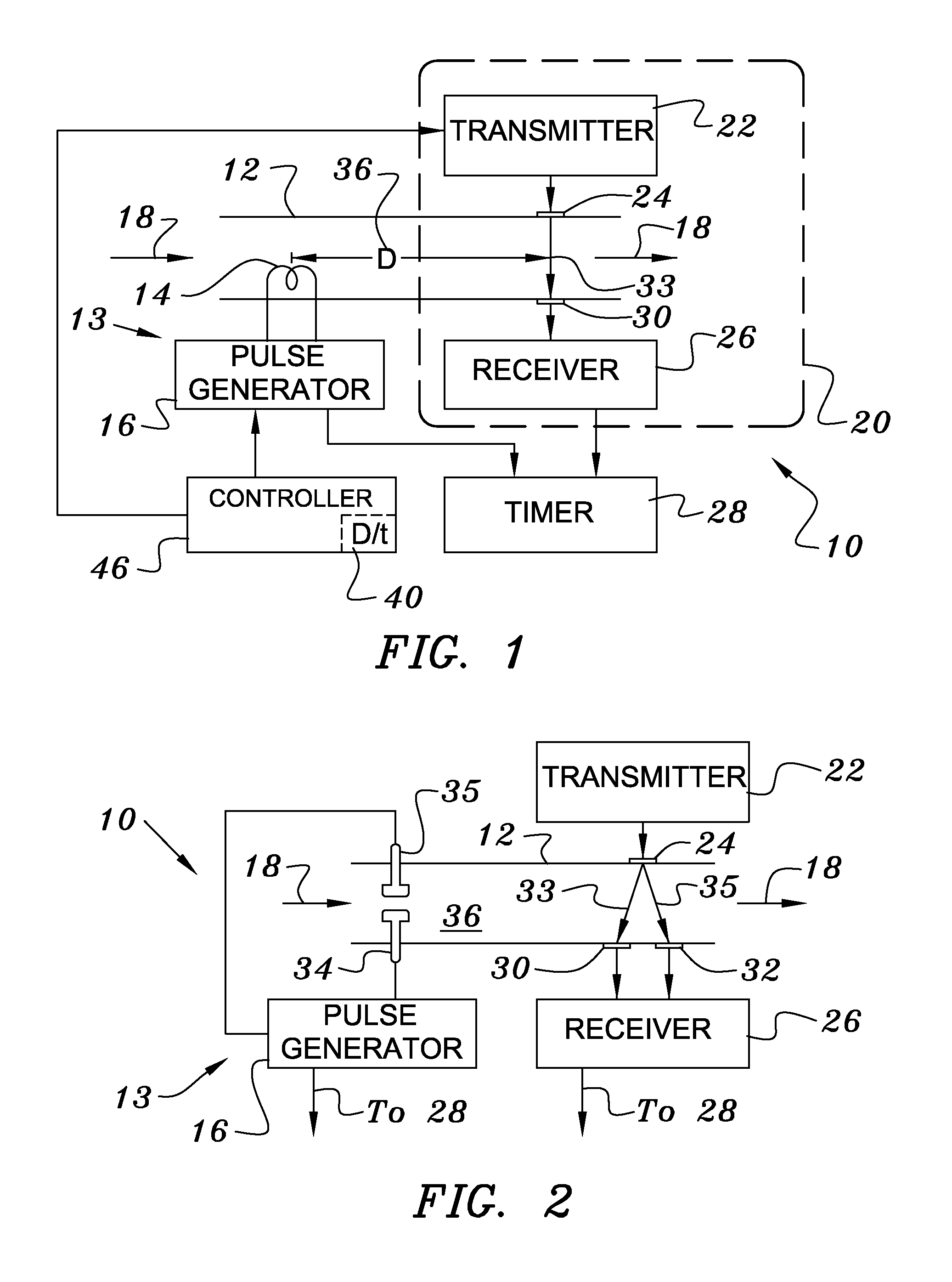
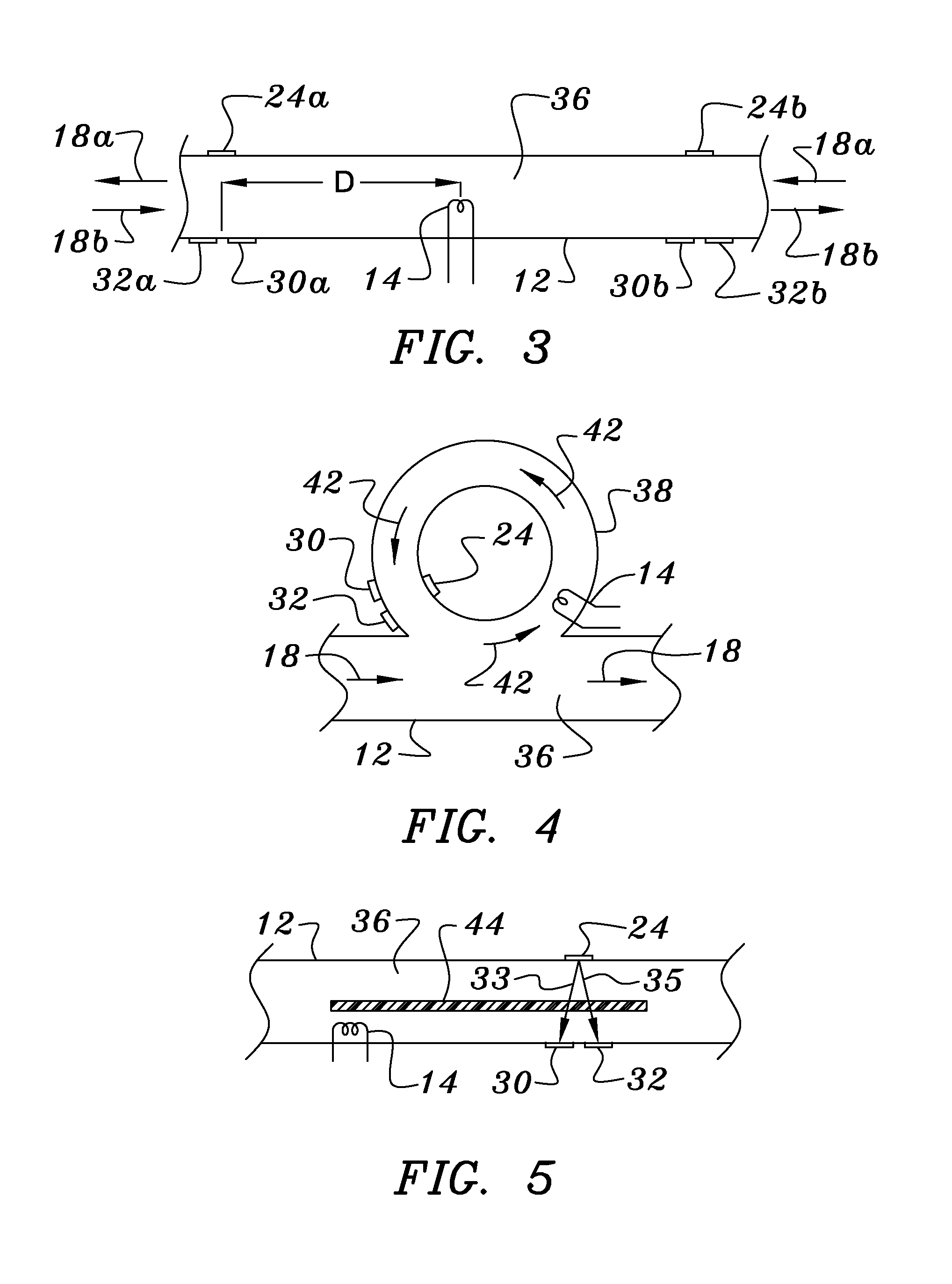
[0020]Turning now to FIG. 1 one finds a schematic depiction of a preferred embodiment of the flow meter of the invention 10. Arrows 18 show the direction of flow of the fluid 36 in a pipe 12. A thermal pulse input means 13, which in this embodiment comprises a resistive heater 14, is disposed upstream of transmitting 24 and receiving 30 transducers that define an acoustic beam 33 transverse to the flow direction 18. The heater 14 is electrically insulated from the pipe 12 if the pipe is electrically conductive, and is energized by a pulse generator 16 that also supplies a bolus-generation time output to a timer 28. The acoustic portion 20 of the apparatus comprises a transmitting transducer 24, energized by a transmitter 22, and a receiving transducer 30 that supplies an output to a receiver 26 that, in turn, supplies a bolus-detection time output to the timer 28.

[0021]In operation of the apparatus of FIG. 1, the pulse generator 16 periodically energizes the heater 14, which heats a...


PUM


Abstract

In thermal pulse flow measurements a relatively small bolus of flowing fluid is heated or cooled and the time required for the bolus to move downstream a known distance is measured. In many fluids, changing the temperature changes the acoustic transmission properties of the bolus from those of the rest of the fluid, so the bolus can be detected when it intersects an acoustic beam. The use of an acoustic beam or beams, which are usually defined between acoustic transmitting receiving transducers, typically provides a high frequency carrier which is modulated by the change in acoustic properties of the bolus when it passes between the two transducers. When compared to conventional thermal measurements, this acoustic approach provides faster response times and can thus be used for measuring higher flow rates.

Description

BACKGROUND OF THE INVENTION[0001]The present invention relates generally to apparatus and methods for measuring the flow rate of a fluid and is applicable to probe and in-line apparatus for making such measurements. More specifically, the invention relates to thermal pulse flow measurements in which a relatively small bolus of flowing fluid is heated or cooled and the time required for the bolus to move downstream a known distance is measured.[0002]Prior art thermal pulsed flow meters typically produce a heat pulse by placing an electric resistance heater in the flowing fluid. This raises the temperature of a small amount of the fluid that is then detected downstream by one or more temperature sensors. By measuring the time interval between the thermal pulse and the detected temperature increase, the fluid flow rate can be determined. The relatively long time required for temperature sensors to respond to the fluid temperature rise relegates this method to measurement of low fluid f...

Claims


Application Information

Patent Timeline
IPC IPC(8): G01F1/708G01F1/7084
CPCG01F1/7044G01F1/7086G01F1/7084
Inventor FELLER, MURRAY F
Owner ONICON INC
Why Eureka
Try Eureka