Two-dimensional image formation apparatus

a two-dimensional image and apparatus technology, applied in the field of two-dimensional image formation apparatus, can solve the problems of increasing the device scale, reducing the brightness of the image displayed on the screen, and so on, and achieve the effect of improving the light use efficiency

Active Publication Date: 2007-09-18
PANASONIC CORP
View PDF15 Cites 33 Cited by
  • Summary
  • Abstract
  • Description
  • Claims
  • Application Information

AI Technical Summary

Benefits of technology

[0013]Therefore, speckle noises existing in an image projected onto a screen can be reduced, resulting in high-quality image display.
[0039]Therefore, it is possible to avoid occurrence of a high-order diffracted light which is scattered at a large angle that is caused by a difference in levels between adjacent concave and convex at the surface of the diffuser, whereby loss of the light quantity due to vignetting caused by the projector lens is dissolved, thereby to improve the light use efficiency.

Problems solved by technology

By the way, in the conventional laser display, since the laser sources which output high-coherent light beams are used as light sources, so-called speckle noise might occur.
However, a mechanism for rotating the diffuser causes an increase in the device scale.
Further, loss of the light scattered by the diffuser causes a reduction in the brightness of the image displayed on the screen.

Method used


Image

  • Two-dimensional image formation apparatus
  • Two-dimensional image formation apparatus
  • Two-dimensional image formation apparatus

Examples


embodiment 1

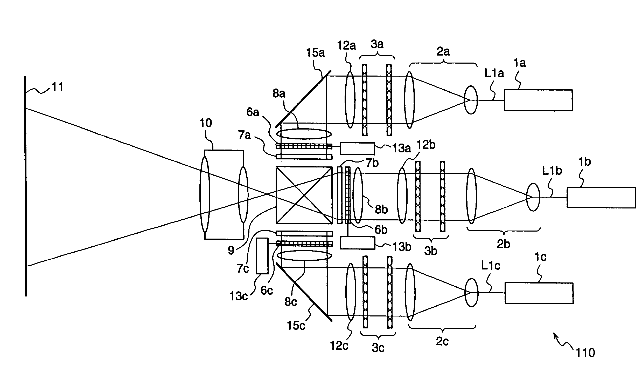
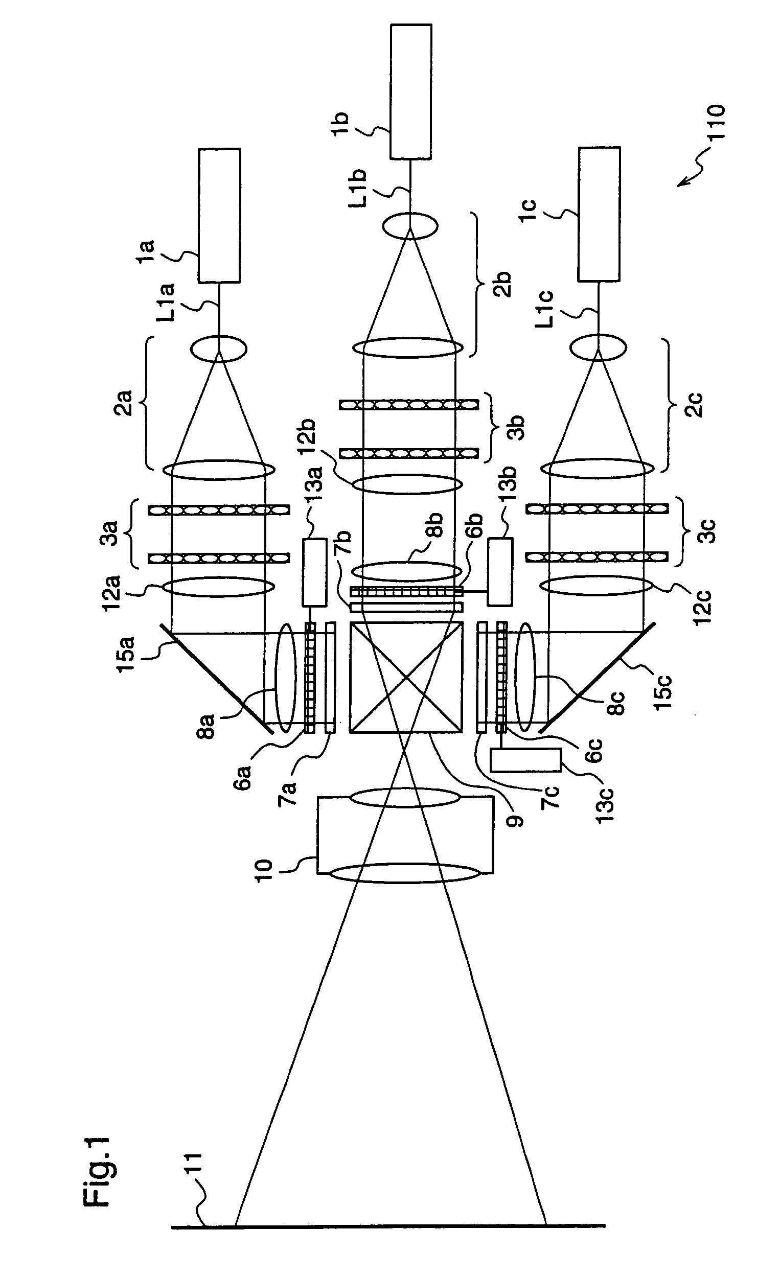
[0051]FIG. 1 is a schematic block diagram for explaining a two-dimensional image formation apparatus according to a first embodiment of the present invention.

[0052]The two-dimensional image formation apparatus 110 shown in FIG. 1 includes laser sources 1a˜1c as coherent light sources corresponding to primary color signals of RGB primary colors, diffusers 6a˜6c for diffusing light beams, and illumination optical systems for irradiating the diffusers 6a˜6c with laser beams L1a˜L1c outputted from the laser sources 1a˜1c, respectively. Further, the two-dimensional image formation apparatus 110 includes diffuser vibration units 13a˜13c for vibrating the respective diffusers 6a˜6c, spatial light modulators 7a˜7c for modulating the light beams that are emitted from the laser sources 1a˜1c and diffused by the diffusers 6a˜6c, which modulators 7a˜7c are constituted by liquid crystal panels or the like, a dichroic prism 9 for multiplexing the light beams that have passed through the spatial l...

embodiment 2

[0089]FIGS. 4(a) and 4(b) are diagrams for explaining a two-dimensional image formation apparatus according to a second embodiment of the present invention. FIG. 4(a) shows a numerical aperture NAin of illumination light, and a numerical aperture NAout of an emitted light from the spatial light modulator 7a, and FIG. 4(b) shows a diffusion angle θ of the diffuser 6a. In the figures, the same or corresponding constituents as those shown in FIG. 3 are given the same reference numerals, and description thereof will be omitted.

[0090]An illumination optical system corresponding to the red laser source 1a of the two-dimensional image formation apparatus 120 according to the second embodiment has a rod type light integrator 14a and a projector lens 15a, instead of the light integrator 3a and the condenser lens 12a of the illumination optical system corresponding to the red laser source 1a of the two-dimensional image formation apparatus 110 according to the first embodiment.

[0091]The rod t...

embodiment 3

[0100]FIG. 5 is a diagram for explaining a two-dimensional image formation apparatus according to a third embodiment of the present invention, illustrating a diffuser as a constituent of the two-dimensional image formation apparatus.

[0101]This third embodiment is different from the first and second embodiments in that the third embodiment employs a pseudo random diffuser 18 having a regular concave-convex configuration at its surface while the first and second embodiments employ a frosted glass diffuser having a random concave-convex configuration at its surface.

[0102]The diffuser according to the first and second embodiments is usually fabricated by randomly roughening the surface of a transparent substrate such as glass or plastic. On the other hand, the pseudo random diffuser 18 according to the third embodiment is fabricated so as to form a concave-convex configuration at its surface, by partitioning the surface of a transparent substrate in a reticular pattern, and processing t...


PUM


Abstract

A two-dimensional image formation apparatus according to the present invention is provided with laser sources (1a)˜(1c), diffusers (6a)˜(6c) for diffusing light, illumination optical systems for irradiating the diffusers (6a)˜(6c) with lights emitted from the laser sources (1a)˜(1c), diffuser vibration units (13a)˜(13c) for vibrating the diffusers (6a)˜(6c), and spatial light modulators (7a)˜(7c) disposed near the diffusers (6a)˜(6c), for modulating the lights emitted from the laser sources (1a)˜(1c) and diffused by the diffusers (6a)˜(6c), wherein the diffusers (6a)˜(6c) are vibrated by the diffuser vibration units (13a)˜(13c) at a velocity that satisfies a relationship, V>d×30 (millimeters / sec), which is established between the grain size d of the diffusers and the vibration speed V of the diffusers, whereby speckle noise existing in an image projected on a screen (11) can be effectively reduced.

Description

[0001]The present application is based on International Application PCT / JP2004 / 010746, filed Jul. 22, 2004, which application is incorporated herein by reference in its entirety.TECHNICAL FIELD[0002]The present invention relates to a two-dimensional image formation apparatus and, more particularly, to an image display apparatus such as a television receiver or a video projector, or an image formation apparatus such as a semiconductor exposure device.BACKGROUND ART[0003]FIG. 7 is a diagram illustrating the schematic structure of a conventional laser display.[0004]This laser display 100 includes laser sources 101a˜101c corresponding to RGB primary colors and light modulators 106a˜106c for subjecting laser beams La˜Lc outputted from the laser sources 101a˜101c to intensity modulation according to primary color signals Sa˜Sc of an input video signal. The laser display 100 further includes a mirror 103 for reflecting the laser beam La modulated by the light modulator 106a, a dichroic mir...

Claims


Application Information

Patent Timeline
Patent Type & Authority Patents(United States)
IPC IPC(8): G02B13/20G02B5/02G02B27/14G02B27/48H04N9/31
CPCG02B5/0221G02B5/0278G02B27/1046G02B27/149G02B27/48H04N9/3105H04N9/3152H04N9/3161H04N9/3197G02B21/0056
Inventor KASAZUMI, KEN'ICHIMIZUUCHI, KIMINORIYAMAMOTO, KAZUHISA
Owner PANASONIC CORP
Why Eureka
Try Eureka