
Cochlear implant electrode array

Inactive Publication Date: 2007-09-18
COCHLEAR LIMITED
View PDF39 Cites 46 Cited by
  • Summary
  • Abstract
  • Description
  • Claims
  • Application Information

AI Technical Summary

Benefits of technology

[0039]In a further embodiment, the stiffness of the tip member can vary along at least a portion of its length from its distal end to its proximal end. In one embodiment, the stiffness of the tip member can vary over the entire length of the tip member or only a portion thereof. The stiffness can increase from the distal end to the proximal end. In one embodiment, the stiffness of the tip member over said portion or its length can increase gradually from its distal end towards to the proximal end. The increase in stiffness can be substantially smooth or increase in a stepwise fashion.
[0042]In another embodiment, the tip member can have a plurality of metallic particles dispersed therethrough. The metallic particles can be substantially evenly dispersed through the tip member. Alternatively, the metallic particles can be non-evenly dispersed throughout the tip member. In one embodiment, the metallic particles can increase in density away from the distal end towards the proximal end of the tip member. By varying the density of the metallic particles, it is possible to vary the relative stiffness of the tip member.
[0048]In another embodiment, the tip member can be formed from, or incorporate as a portion thereof, a polymeric coating which becomes softer, and so increases in resilient flexibility, in the presence of moisture or body heat.
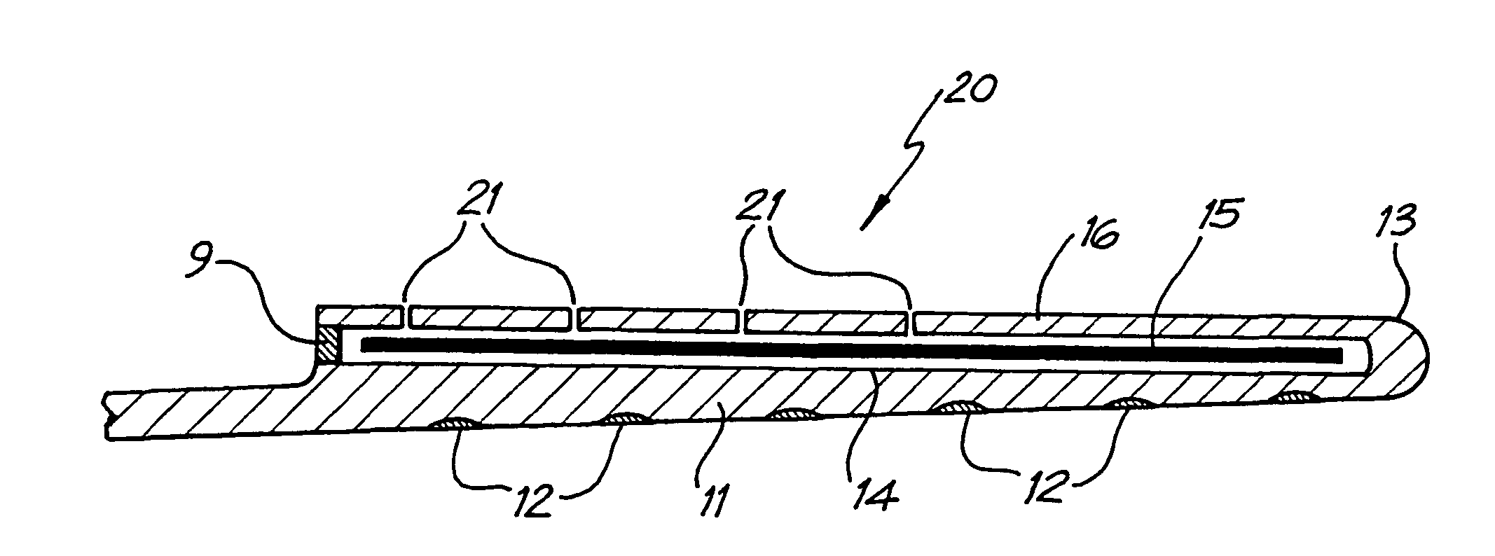
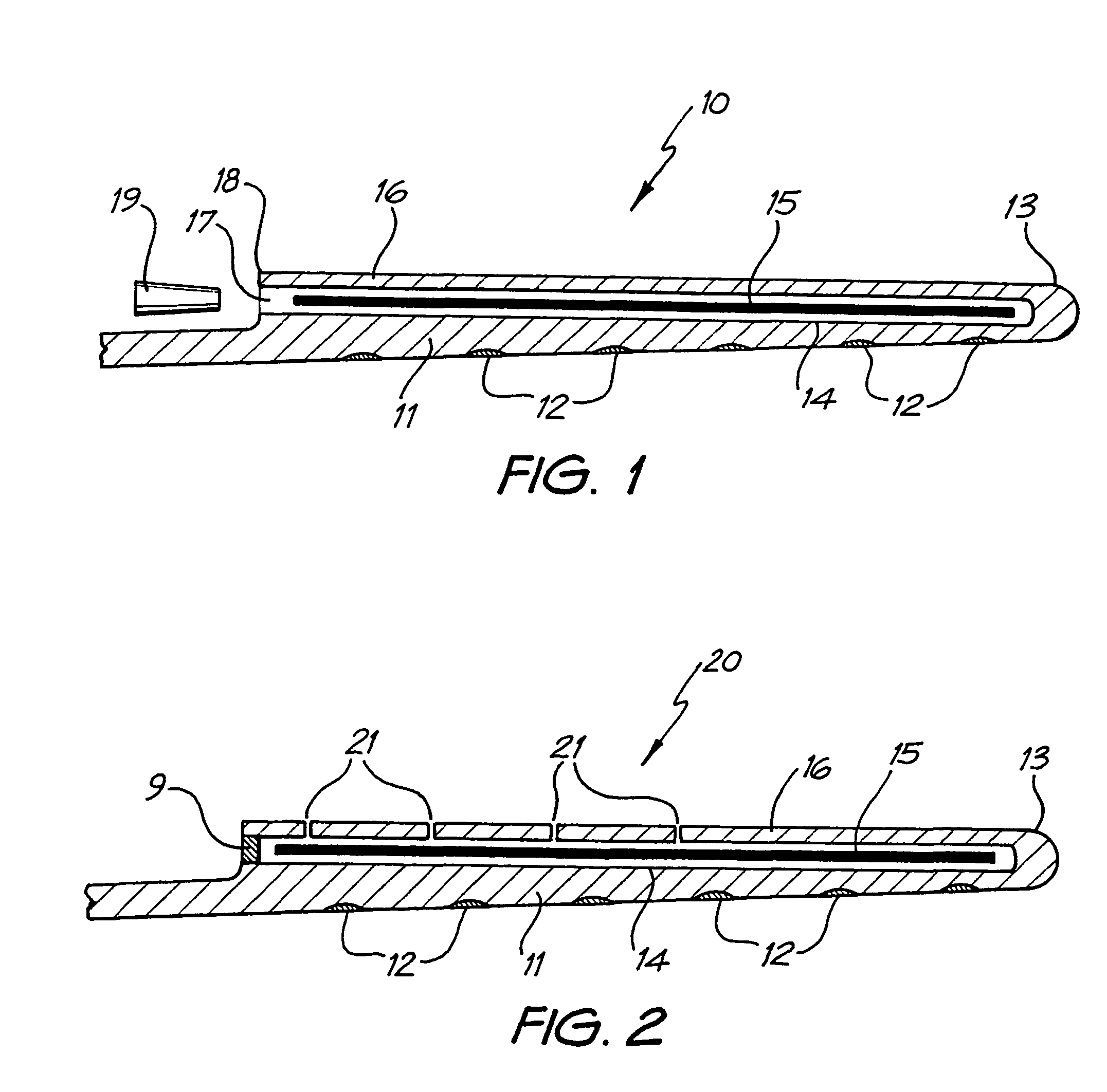
[0064]In one embodiment, the slit most distal the first end of the elongate member can allow a greater rate of fluid ingress through the outer layer than its adjacent slit positioned closer to said first end or vice versa. As such, the bioresorbable material beneath this slit preferably begins to dissolve or soften before the remainder of the stiffening element so allowing the elongate member to begin to firstly move from its first configuration to its second configuration at or adjacent the position of this most distal or most proximal slit.
[0066]In one embodiment, the slits or other fluid ingress means can be sealable with a bioresorbable material. The bioresorbable material preferably softens and / or dissolves on exposure to a fluid, such as cochlear fluid, to allow ingress of the fluid into the elongate member. In this embodiment, the slits or other fluid ingress means can be sealed with the same or a different quantity and / or the same or different thicknesses of bioresorbable material. Variations in thickness and / or quantity of the bioresorbable material provide a means of varying the rate of ultimate dissolution of the stiffening element of the device.
[0073]In one embodiment, the lead can extend from the elongate member to the stimulator means or at least the housing thereof. In one embodiment, the lead is continuous with no electrical connectors, at least external the housing of the stimulator means, required to connect the wires extending from the electrodes to the stimulator means. One advantage of this arrangement is that there is no requirement for the surgeon implanting the device to make the necessary electrical connection between the wires extending from the electrodes and the stimulator means.

Problems solved by technology

Of these types, conductive hearing loss occurs where the normal mechanical pathways for sound to reach the hair cells in the cochlea are impeded, for example, by damage to the ossicles.
In many people who are profoundly deaf, however, the reason for deafness is sensorineural hearing loss.
These people are thus unable to derive suitable benefit from conventional hearing aid systems, because there is damage to or absence of the mechanism for nerve impulses to be generated from sound in the normal manner.
Moreover, the current from each electrode may flow in all directions, and the electrical fields corresponding to adjacent electrodes may overlap, thereby causing cross-electrode interference.
This is a challenge, as the array needs to be shaped such that it assumes a curved shape to conform with the shape of the modiola and must also be shaped such that the insertion process causes minimal trauma to the sensitive structures of the cochlea.
A disadvantage with use of such bioresorbable materials is that, due to the generally wet nature of the surgical environment, the polymer can dissolve or soften before the electrode array is appropriately positioned, causing difficulties in placement and insertion procedures.

Method used


Image

  • Cochlear implant electrode array
  • Cochlear implant electrode array
  • Cochlear implant electrode array

Examples


Embodiment Construction

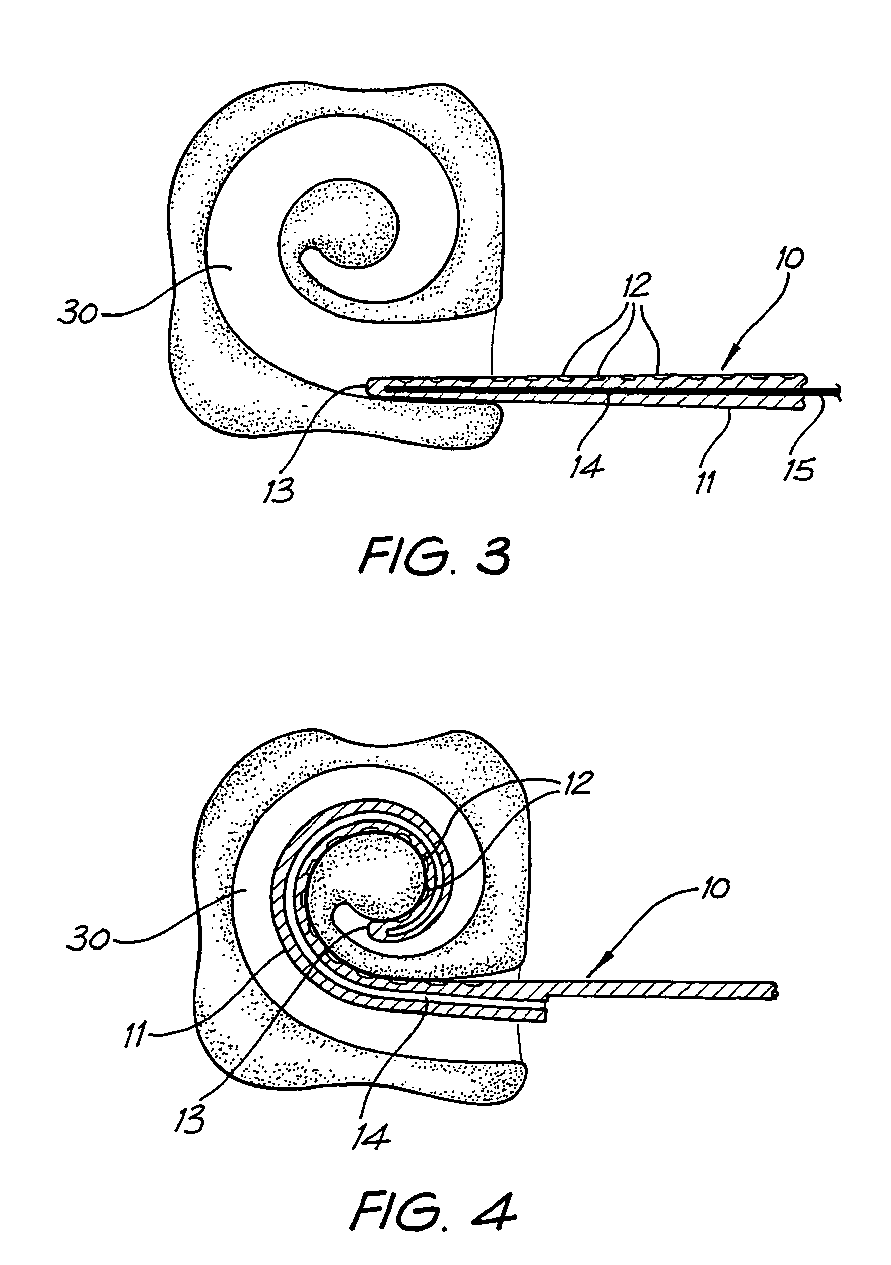
[0088]One embodiment of a cochlear implant electrode assembly is depicted generally as 10 in FIGS. 1, 3 and 4.

[0089]The depicted electrode assembly 10 preferably has an electrical lead extending back to a stimulator / receiver housing. In considering this invention, it is to be understood that each electrode may have one or more wires (not depicted) electrically connected thereto and extending from each respective electrode back through the lead to the stimulator / receiver. The use of a stimulator / receiver as described herein is known in the art and the present invention can be used with any such stimulator / receiver as known in the art.

[0090]The assembly 10 comprises an elongate electrode carrier member 11 having a plurality of electrodes 12 mounted thereon. For the purposes of clarity, the electrodes 12 depicted in FIGS. 1, 2 and 5 are not necessarily shown to scale. The depicted elongate member 11 is preformed from a resiliently flexible silicone with memory and is preformed to a cur...


PUM


Abstract

A cochlear implant electrode assembly (10) comprising an elongate electrode carrier member (11), a bioresorbable stiffening element (15) and an outer layer (16) surrounding the stiffening element (15). The carrier member (11) is made of a resiliently flexible first material and has a plurality of electrodes (12) mounted thereon and has a first configuration selected to allow it to be inserted into an implantee's cochlea, and at least a second configuration wherein it is curved to match a surface of the cochlea. The bioresorbable stiffening element (15) has a configuration selected for biassing the elongate member (11) into the first configuratin and is made of a second material relatively stiffer than the first material and which dissolves or softens on exposure to cochlear fluids to permit the elongate member (11) to at least approach or adopt the second configuration. The outer layer (16) surrounding the stiffening element (15) is made of a material sufficiently resiliently flexible to allow the elongate member (11) to at least approach or adopt the second configuration. The outer layer (16) has a first rate of cochlear fluid ingress therethrough and has at least one fluid ingress means (21) formed therein. The rate of cochlear fluid ingress through the fluid ingress means (21) is greater than the first rate of cochlear fluid ingress through the outer layer (16).

Description

FIELD OF THE INVENTION[0001]The present invention relates to an implantable device and, in particular, to an implantable cochlear electrode incorporating a bioresorbable stylet.BACKGROUND OF THE INVENTION[0002]Hearing loss, which may be due to many different causes, is generally of two types, conductive and sensorineural. Of these types, conductive hearing loss occurs where the normal mechanical pathways for sound to reach the hair cells in the cochlea are impeded, for example, by damage to the ossicles. Conductive hearing loss may often be helped by use of conventional hearing aid systems, which amplify sound so that acoustic information does reach the cochlea and the hair cells.[0003]In many people who are profoundly deaf, however, the reason for deafness is sensorineural hearing loss. This type of hearing loss is due to the absence of, or destruction of, the hair cells in the cochlea which transduce acoustic signals into nerve impulses. These people are thus unable to derive suit...

Claims


Application Information

Patent Timeline
IPC IPC(8): A61N1/05A61F11/00A61F2/18A61F11/04
CPCA61N1/0541A61F11/004A61F11/20
Inventor DADD, FYSHDARLEY, IANGIBSON, PETERPARKER, JOHNTREABA, CLAUDIU
Owner COCHLEAR LIMITED
Learn More