Surgical drape and head for wound treatment

a surgical drape and head technology, applied in the field of surgical drapes and heads, can solve the problems of difficult to handle the highly pliable and adhesive film after the releasable layer, and achieve the effects of preventing air leakage, improving handling characteristics, and substantially improving handling characteristics

Inactive Publication Date: 2007-09-25
KCI LICENSING INC
View PDF112 Cites 182 Cited by
  • Summary
  • Abstract
  • Description
  • Claims
  • Application Information

AI Technical Summary

Benefits of technology

[0011]Although the strengthening layer does somewhat improve the handling characteristics, this is not a complete answer to the problem. However, the handling characteristics are substantially improved by providing a protective layer which is in at least two portions, one of which is in the form of a strip, e.g. one extending parallel to the lateral edges of the drape, and covering the peripheral area around the aperture through the drape. By providing a flap on this portion of the releasable layer, it can be stripped off initially so that the drape is first positioned around the device which is to pass through the aperture, and then the remaining part of the protective releasable layer is stripped off to adhere the drape to the patient's skin around the area to be treated.
[0012]In a preferred form of the invention in which negative pressure therapy is applied to a wound area, the surgical drape described above is combined with a suction head having a connector piece which is adapted to be connected to a suction tube. Thus, in this embodiment, the suction head can be adhered to the patient's skin in the area of the wound after removing the strip of protective releasable layer, and then the remaining part of the drape affixed to the patient's skin. In this way, the suction head is held firmly in place and, at the same time, seals the suction head to the wound area and prevents leakage of air from atmosphere into the wound area.
[0013]The invention also includes a suction head having a design which facilitates the suction of fluid from a wound area.
[0014]According to a further feature of the invention, therefore, a suction head for applying suction to a wound may also be used as a head to instill fluids to a wound from a fluid reservoir similar to an intravenous solution bag. The area of which comprises a generally planar flange portion and a tubular connector piece on a first face, for connecting a fluid reservoir tube to a fluid reservoir through the flange portion to the other face, said other face having projections defining flow channels facilitating flow of fluid towards a wound
[0015]According to a further feature of the invention, therefore, there is provided a suction head for applying suction to a wound area which comprises a generally planar flange portion and a tubular connector piece on a first face, for connecting a suction tube to an aperture through the flange portion to the other face, said other face having projections defining flow channels facilitating flow of fluid towards said aperture.

Problems solved by technology

While an aperture could be cut at the desired position through the layers to accommodate a catheter or a device such as those described in our above-mentioned applications, it is difficult to handle the highly pliable and adhesive film after the releasable layer has been stripped off.

Method used


Image

  • Surgical drape and head for wound treatment
  • Surgical drape and head for wound treatment
  • Surgical drape and head for wound treatment

Examples


Embodiment Construction

[0030]Although those of ordinary skill in the art will readily recognize many alternative embodiments, especially in light of the illustrations provided herein, this detailed description is exemplary of the preferred embodiment of the present invention, the scope of which is limited only by the claims appended hereto.

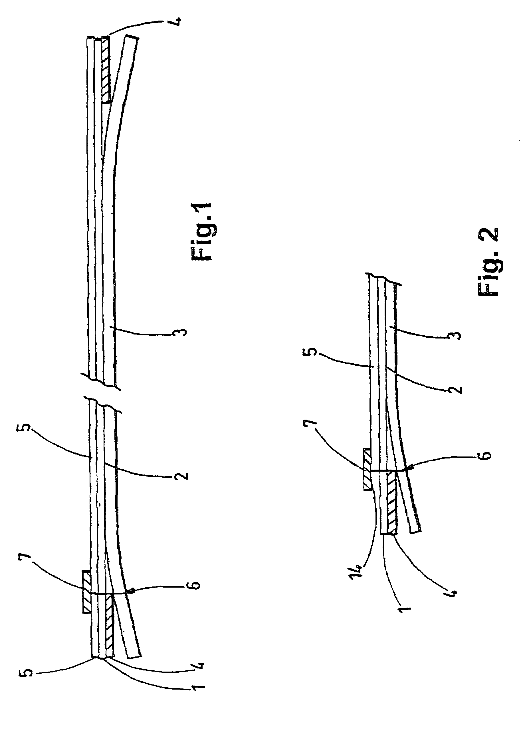
[0031]Referring to FIGS. 1 and 2 of the accompanying drawings, a conventional laminate for use as a surgical drape comprises a thin, flexible, transparent film 1 which is adhesive-coated on one face 2, normally with a high-tack pressure-sensitive adhesive, and is protected with a releasable layer 3. The thin plastic film is conveniently of polyurethane because is transmits moisture. Layer 3 is normally considerably thicker than film 1 and is coated on the surface adjacent to the adhesive with a releasable material such as a silicone to facilitate stripping away from the adhesive-coated film.

[0032]In order to facilitate removal of the adhesive-coated film prior to use of...


PUM


Abstract

A wound therapy device comprising a head and a surgical drape. The head comprises a planar flange portion and a tubular connector piece on a first face that communicates with an aperture extending to a second face. The second face is formed with projections that define flow channels for facilitating flow of liquids to and from the aperture. The device may provide medicated fluid to the wound evenly while withdrawing wound exudates.

Description

RELATED APPLICATIONS[0001]This application is a continuation-in-part of U.S. application Ser. No. 10 / 366,227, filed on Feb. 13, 2003, now U.S. Pat. No. 6,814,079 which is a continuation of U.S. application Ser. No. 09 / 835,500, filed on Apr. 16, 2001, now U.S. Pat. No. 6,553,998, which is a continuation of Ser. No. 09 / 350,581, filed on Jul. 9, 1999, now U.S. Pat. No. 6,345,623, which is a continuation, under 35 U.S.C. §120 of PCT international application number PCT / GB98 / 02713 filed Sep. 9, 1998 and designating the United States, which claims priority to Great Britain patent application No. 9719520.0 filed Sep. 12, 1997. By this reference, the full disclosure of U.S. application Ser. No. 09 / 350,581, PCT international application No. PCT / GB98 / 02713, and Great Britain patent application No. 9719520.0 are incorporated herein as though fully set forth in their respective entirety.FIELD OF THE INVENTION[0002]This invention relates in general to surgical drapes and heads, and more particul...

Claims


Application Information

Patent Timeline
Patent Type & Authority Patents(United States)
IPC IPC(8): A61B19/00A61B19/08A61B46/23A61F13/02A61M1/00
CPCA61B19/08A61B19/10A61F13/023A61M1/0088A61B2019/085A61B2019/106A61B2217/005A61M1/0084A61B46/23A61B2046/236A61B46/00A61B2046/205A61M1/85A61M1/92A61M1/915
Inventor HEATON, KEITH PATRICKHUNT, KENNETH WILLIAMSANDERS, TERYL BLANE
Owner KCI LICENSING INC
Why Eureka
Try Eureka