Ribbed telescope mirrors with thermal gradient control

a technology of thermal gradient control and telescope mirrors, applied in the direction of mirrors, mountings, instruments, etc., can solve the problems of astronomical telescopes that operate on earth that cannot produce sharp images, the structure of mirrors became very soft and required internal support, and the mirrors are exposed to heat loads during optical polishing

Inactive Publication Date: 2007-09-25
SCHWARTZ RICHARD A
View PDF27 Cites 8 Cited by
  • Summary
  • Abstract
  • Description
  • Claims
  • Application Information

AI Technical Summary

Benefits of technology

[0007]The present invention is a method of fabricating ribbed mirrors which allows heat to be conducted past the glass during optical polishing and application of coatings. The present invention permits the use of ordinary, inexpensive plate glass for fabrication of ribbed telescope mirrors. The method is applicable to mirrors which have a mirror plate and a supporting rib, joined together at an interior angle. The method comprises placing a fillet of thermally conductive material in thermal contact with the mirror plate and the supporting rib at the interior angle. Thermal contact means that heat easily flows across the part boundary. It is not necessarily the same as mechanical contact or attachment. The preferred thermally conductive material is RTV (room temperature vulcanizing) silicone such as GE-II, manufactured by GE Silicones of Waterford, N.Y. The RTV silicone can be mixed with a powdered or granular heat conductor such as copper, diamond dust, aluminum oxide and silicon carbide. Alternatively, the thermally conductive material can be made from a segment or bridge of thermally conductive rigid material, such as cooper, diamond, beryllium, silver or aluminum, possibly having an exterior angle, and a thermally conductive plastic such as RTV silicone, thermally conductive grease or thermally conductive epoxy applied to the surfaces of the exterior angle or the angled end of the bridge. Another alternative construction utilizes segments of thermally conductive rod, such as copper, diamond, beryllium, silver or aluminum bent to approximate the interior angle, placed close to the interior angle with a fillet of thermally conductive grease, silicone or epoxy between the rod and the mirror and the rod and the rib. Yet another alternative construction utilizes a thermally conductive rod, such as copper, diamond, beryllium, silver or aluminum, placed close to the interior angle with a fillet of thermally conductive grease, silicone or epoxy between the rod and the mirror and the rod and the rib.

Problems solved by technology

Moreover, astronomical telescopes that operate on earth cannot produce sharp images until the mirror surface cools to nearly the same temperature as the ambient air.
As a result, his mirror structure became very soft and required internal support during the fusing process.
Unfortunately, mirrors are exposed to heat loads during optical polishing and during application of some kinds of coating.
If the mirror is not made of an expensive material with low coefficient of expansion, thermal gradients will result in mechanical stress that can crack the glass.
Because glass is a poor heat conductor, applied heat loads (especially transient heat loads) lead to large thermal gradients—especially where heat flows around a sharp corner.

Method used


Image

  • Ribbed telescope mirrors with thermal gradient control
  • Ribbed telescope mirrors with thermal gradient control
  • Ribbed telescope mirrors with thermal gradient control

Examples


fifth embodiment

[0024]FIG. 6 is a three dimensional sketch showing a mirror plate 10 attached to a rib 20 with a fifth embodiment composite, segmented fillet 135 between the poorly mated surface 145 of the heat bridge 140 and the surfaces of the mirror 150 and rib 152. The heat conducting bridge 140 is made from heavy copper, silver or aluminum wire bent at an angle to approximate the interior angle 80. As shown on the Figure, not all the bridges 140 are necessarily the same length. The bridges 140 are thermally connected to the surfaces 150 with fillets of thermally conductive grease, silicone or epoxy 155.

sixth embodiment

[0025]FIGS. 7 and 8 show cross sections of joints between a mirror plate 10 and a rib 20 with a sixth embodiment continuous, composite fillet 160 of rigid tube or rod 165 and plastic heat conductor of thermally conductive grease, silicone or epoxy 155. The tube or rod 165 is preferably made from copper, silver or aluminum. Note that there will probably be a void 170 in the corner 85.

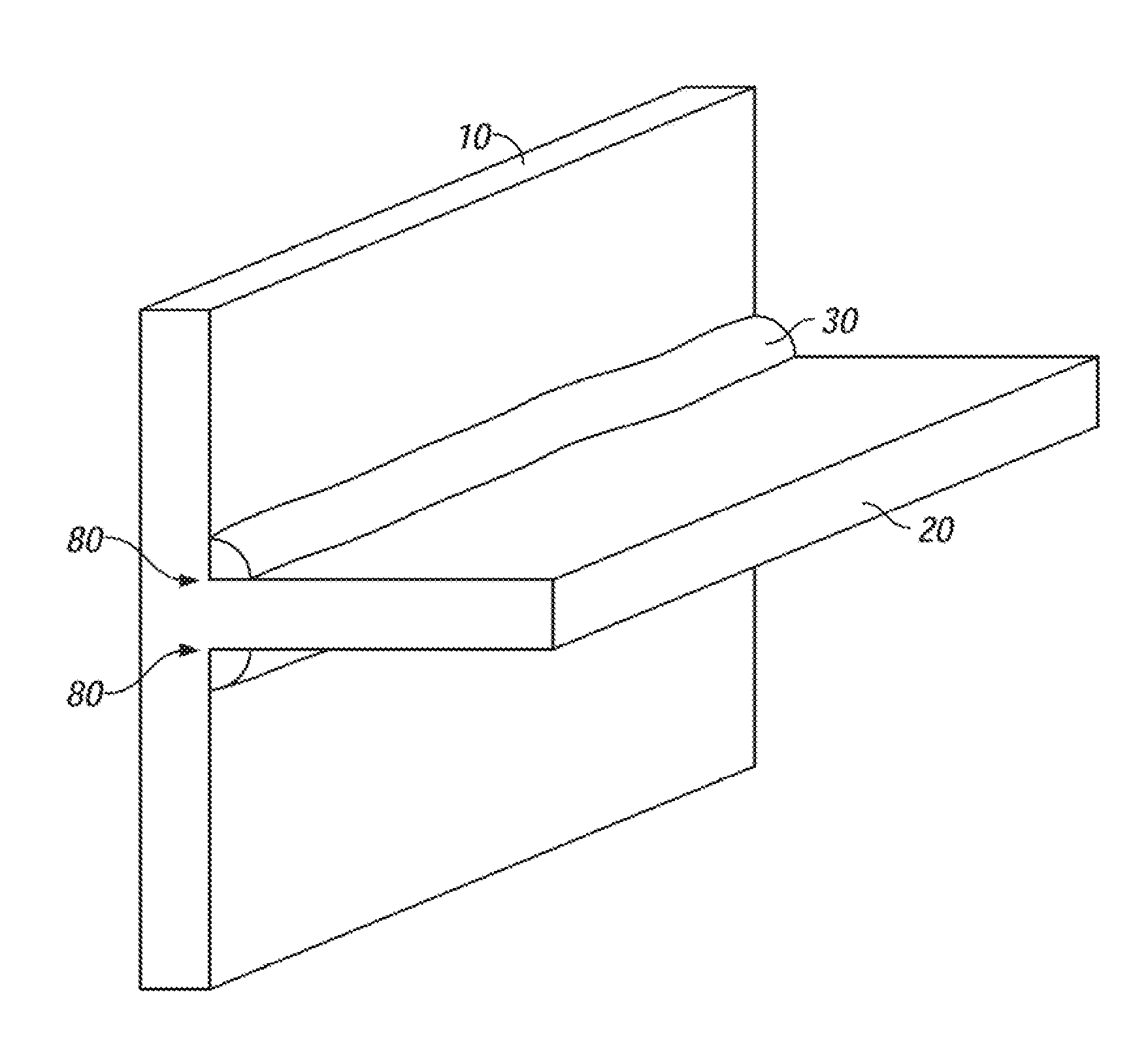
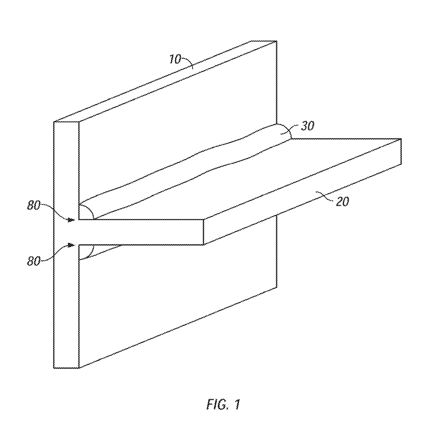
[0026]Thus, what results from this method is an improved, ribbed telescope mirror with a fillet of thermally conductive material 30, 60, 70, 100, 110, 145, 170 in thermal contact with the mirror plate 10 and the supporting rib 20 at the interior angle 80 between the mirror plate 10 and supporting rib 20. The fillet 30, 60, 70, 100, 110, 145, 170 can be made of all the materials identified above.

[0027]Those most familiar with the art to which this invention pertains will readily appreciate that grease can readily be removed from any surface with rags and solvent. Also, RTV is easy to remove from surfaces ...


PUM

PropertyMeasurementUnit
thermally conductiveaaaaaaaaaa
temperatureaaaaaaaaaa
exterior angleaaaaaaaaaa

Abstract

Ribbed mirrors allowing heat to be conducted past the glass during optical polish and application of coatings and methods of fabricating same. The method comprises placing a bridge of thermally conductive material in thermal contact with the mirror plate and the supporting rib at the interior angle. The preferred thermally conductive material is RTV silicone. However, the RTV silicone can be mixed with a powdered heat conductor such as diamond dust, aluminum oxide and silicon carbide. Alternatively, the thermally conductive fillet can be made from a segment of thermally conductive rigid material, such as copper, diamond, beryllium, silver and aluminum having an exterior angle matching the interior angle and a thermally conductive plastic such as RTV silicone or thermally conductive grease, silicone or epoxy applied to surfaces of the exterior angle.

Description

BACKGROUND OF THE INVENTION[0001]The present invention relates to the field of telescope mirror fabrication and more particularly to a method for reducing the cracking of ribbed mirrors during thermal processing.[0002]There is a great motivation to use ribbed mirrors in telescopes. Ribbed mirrors are lightweight, less glass is needed and commonly available thin glass can be utilized. Ribbed mirrors are stiffer than thin mirrors, which simplifies the supporting structure and reduces dynamic disturbance and vibration. Ribbed mirrors are cheaper to produce, cheaper to launch into orbit, and can be aimed more quickly with less power. Moreover, astronomical telescopes that operate on earth cannot produce sharp images until the mirror surface cools to nearly the same temperature as the ambient air. Ribbed mirrors cool more rapidly than thick mirrors.[0003]George Ritchey, who fabricated the Mt. Wilson 100, a solid mirror, experimented with ribbed mirrors in France in the late 1920's. The r...

Claims


Application Information

Patent Timeline
Patent Type & Authority Patents(United States)
IPC IPC(8): G02B7/182
CPCG02B7/183Y10S359/90
Inventor SCHWARTZ, RICHARD A.
Owner SCHWARTZ RICHARD A
Why Eureka
Try Eureka