Meander line capacitively-loaded magnetic dipole antenna

a capacitively loaded, magnetic dipole antenna technology, applied in the direction of antennas, antenna details, antenna feed intermediates, etc., can solve the problems of counterpoise being susceptible to changes in the design and location of proximate circuitry, radiation patterns and communications efficiency can be detrimentally impacted, and both feeds are likely to pick up the same noise, so as to reduce the susceptibility of counterpoise, improve receiver sensitivity, and reduce the amount of radiation-associated curren

Inactive Publication Date: 2007-09-25
KYOCERA CORP
View PDF23 Cites 19 Cited by
  • Summary
  • Abstract
  • Description
  • Claims
  • Application Information

AI Technical Summary

Benefits of technology

[0009]The present invention discloses a capacitively-loaded magnetic dipole radiator antenna. The antenna is balanced, to minimize the susceptibility of the counterpoise to detuning effects that degrade the far-field electro-magnetic patterns. The balanced antenna also acts to reduce the amount of radiation-associated current in the groundplane, thus improving receiver sensitivity. The antenna loop is a capacitively-loaded magnetic dipole, to confine the electric field and so reduce the overall size (length) of the radiating elements. Further, the antenna's radiator is made from a meander line structure, to reduce to overall form factor of the antenna.

Problems solved by technology

Many of the above-mentioned conventional wireless telephones use a monopole or single-radiator design with an unbalanced signal feed.
However, the counterpoise is susceptible to changes in the design and location of proximate circuitry, and interaction with proximate objects when in use, i.e., a nearby wall or the manner in which the telephone is held.
As a result of the susceptibility of the counterpoise, the radiation patterns and communications efficiency can be detrimentally impacted.
Both feeds are likely to pick up the same noise and, thus, be cancelled.

Method used


Image

  • Meander line capacitively-loaded magnetic dipole antenna
  • Meander line capacitively-loaded magnetic dipole antenna
  • Meander line capacitively-loaded magnetic dipole antenna

Examples


Embodiment Construction

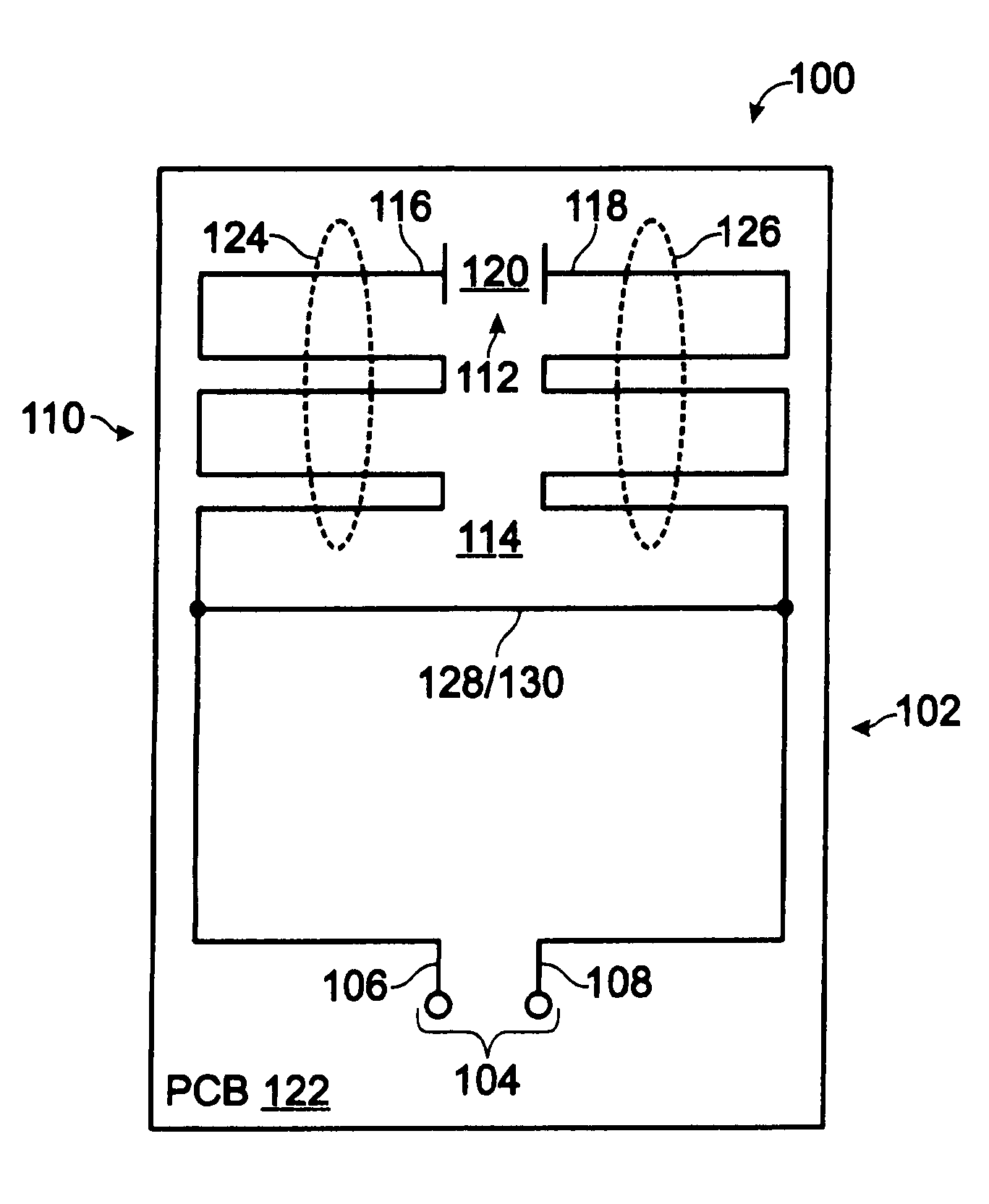
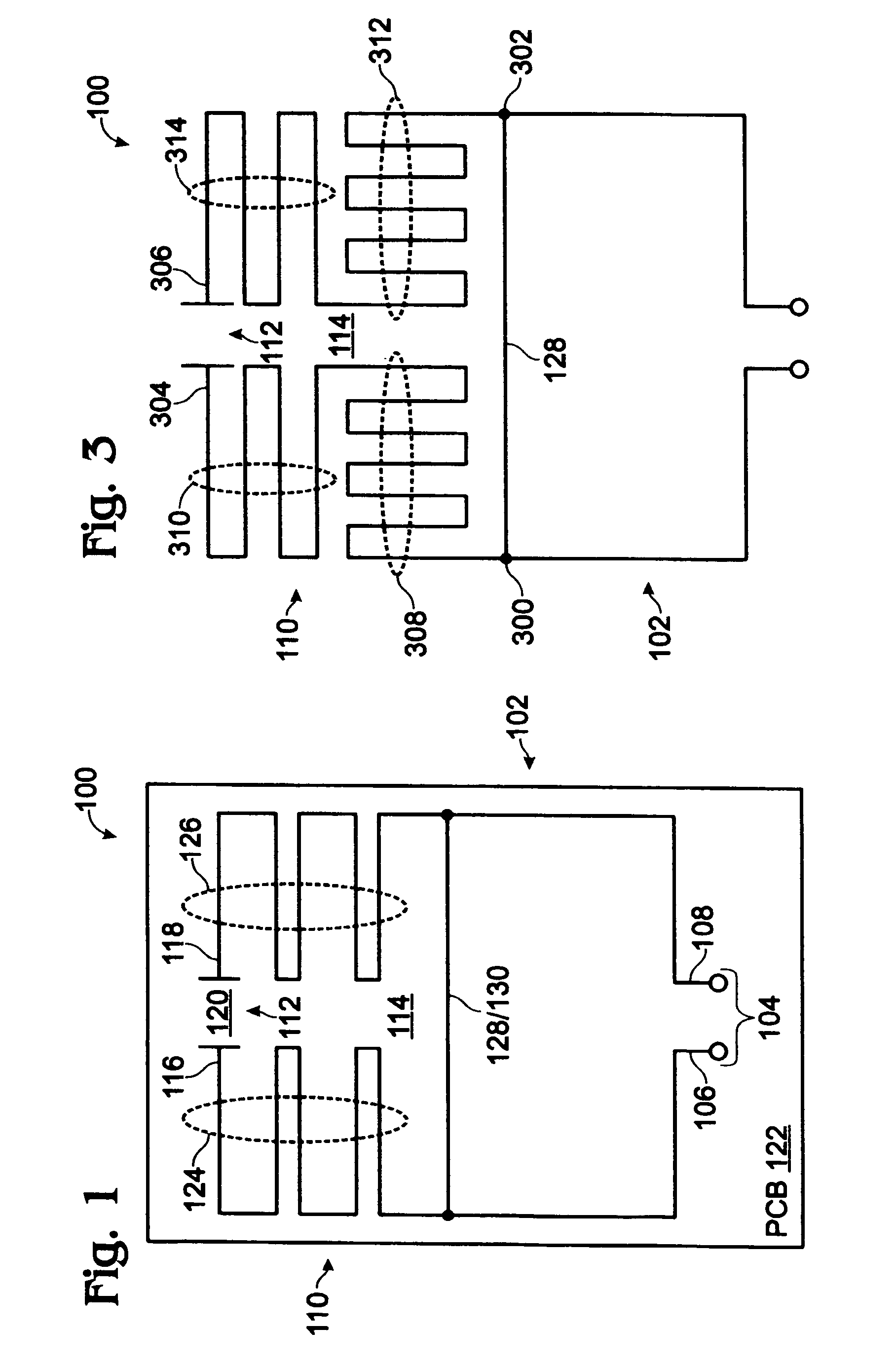
[0031]FIG. 1 is a plan view of a meander line capacitively-loaded magnetic dipole antenna. The antenna 100 comprises a transformer loop 102 having a balanced feed interface 104. The balanced feed interface 104 accepts a positive signal on line 106 and a negative signal (considered with respect to the positive signal) on line 108. In some aspects, the signal on line 108 is 180 degrees out of phase with the signal on line 106. The antenna 100 also comprises a meander line capacitively-loaded magnetic dipole radiator 110.

[0032]The meander line capacitively-loaded magnetic dipole radiator 110 comprises an electric field bridge 112. The meander line capacitively-loaded magnetic dipole radiator 110 comprises a quasi loop 114 with a first end 116 and a second end 118. The electric field bridge 112 is interposed between the quasi loop first end 116 and the second end 118. As shown, the bridge 112 is a dielectric gap capacitor, where the dielectric is the material 120 in the bridge. For exam...


PUM


Abstract

A meander line capacitively-loaded magnetic dipole antenna is disclosed. The antenna includes a transformer loop having a balanced feed interface, and a meander line capacitively-loaded magnetic dipole radiator. The meander line capacitively-loaded magnetic dipole radiator also includes an electric field bridge. For example, the meander line capacitively-loaded magnetic dipole radiator may include a quasi loop with a first end and a second end, with the electric field bridge interposed between the quasi loop first and second ends. The electric field bridge may be an element such as a dielectric gap, lumped element, circuit board surface-mounted, ferroelectric tunable, or a microelectromechanical system (MEMS) capacitor. The transformer loop has a radiator interface coupled to a quasi loop transformer interface. In one aspect, the coupled interfaces are a shared perimeter portion shared by both loops.

Description

FIELD OF THE INVENTION[0001]This invention generally relates to wireless communications and, more particularly, to a meander line capacitively-loaded magnetic dipole antenna with a balanced feed.BACKGROUND OF THE INVENTION[0002]The size of portable wireless communications devices, such as telephones, continues to shrink, even as more functionality is added. As a result, the designers must increase the performance of components or device subsystems and reduce their size, while packaging these components in inconvenient locations. One such critical component is the wireless communications antenna. This antenna may be connected to a telephone transceiver, for example, or a global positioning system (GPS) receiver.[0003]State-of-the-art wireless telephones are expected to operate in a number of different communication bands. In the US, the cellular band (AMPS), at around 850 megahertz (MHz), and the PCS (Personal Communication System) band, at around 1900 MHz, are used. Other communicat...

Claims


Application Information

Patent Timeline
Patent Type & Authority Patents(United States)
IPC IPC(8): H01Q9/16H01Q1/36H01Q7/00
CPCH01Q9/16H01Q9/26
Inventor OZKAR, METEPOILASNE, GREGORY
Owner KYOCERA CORP
Why Eureka
Try Eureka