Hermetically sealed electrolytic capacitor

a capacitor and hermetically sealed technology, applied in the field of electrolytic capacitors, can solve the problems of non-hermetically sealed capacitors, leakage around conventional non-hermetically sealed polymeric seals, and failure of capacitors containing electrolyte solutions, etc., and achieve the effect of reducing the cost of aluminum to glass seals and not being able to achieve hermetically sealed capacitors

Active Publication Date: 2007-09-25
CORNELL DUBILIER MARKETING
View PDF29 Cites 25 Cited by
  • Summary
  • Abstract
  • Description
  • Claims
  • Application Information

AI Technical Summary

Benefits of technology

[0012]In the present invention, it is possible to provide mechanical isolation between the hermetic seal and the liquid seal. An embodiment of the invention features physical separation of the hermetic seal and the liquid seal, while maintaining a flexible electrical conduit between the dry side of the terminal and the inner portion of the glass seal. This feature allows the liquid seal to flex, without putting mechanical stress on the hermetic seal, and can be a significant advantage. For example, at high internal pressure conditions within the capacitor unit, the terminal is free to move closer to the underside of the lid as it further compresses the elastomer seal, and creates a virtually “leakproof” seal within the full range of pressure levels typically experienced within a capacitor unit.
[0013]The capacitor of the present invention is hermetically sealed, which is defined as having a permeability to helium gas of 10-7 cc / second or less, at 25° C. and one atmosphere of differential pressure.
[0014]The capacitor is housed in a case, which is a receptacle having an opening at one end. The case is made from a material that is substantially impermeable to gases. By way of example, the case may be made out of metal, in particular, steels (stainless or other alloys), copper, tantalum, aluminum, titanium, niobium, nickel, iron, and zinc. Preferably, the case is made out of steel or steel alloys, including cold-rolled steel, mild steel and stainless steel, tantalum, titanium and niobium. If the case material is susceptible to corrosion, either internally or externally, the material may be coated, plated or provided with other protective treatment, as is known to those skilled in the art.
[0015]An advantage of the present invention is that its performance is not dependent upon the case having any particular shape. By way of example, the case may be in the shape of a cylinder, rectangular prism or parallelepiped.
[0016]A capacitor element is positioned inside the case. The capacitor element is made up of an anode, a cathode, a dielectric and an electrolyte solution, forming a capacitor capable of supporting a direct current potential, and thereby storing an electrical charge and energy. The anode is a valve metal upon which resides a dielectric, which is generally grown from the base metal in an anodizing electrochemical bath. The anode metal contacts the dielectric on its positively charged side, and the electrolyte contacts the dielectric on its negatively-charged side and conveys the charge to the cathode.
[0017]The potentials of the anode and cathode may be conducted to positive and negative terminals, respectively, by means of a tab, wire or other metallic conductor. With respect to the cathode, the capacitor case may be used for the negative terminal.

Problems solved by technology

Capacitors containing an electrolyte solution are subject to failure caused by leakage of the electrolyte liquid or vapor.
Consequently, leaks may occur around conventional non-hermetic polymeric seals, where the terminal, for example a wire, protrudes from the capacitor housing.
In the situation of an aluminum case, it has not proven economical, however, to provide a hermetic, aluminum to glass seal, due in part to the significant difference in the thermal coefficient of expansion of the glass or ceramic material used to construct the seal and the thermal coefficient of expansion of aluminum.
Either of these two situations could result in undesirable electrical current flow between the high electrical potential of the inner-metal and the low potential of the outer-metal if the electrolyte is allowed access to all regions of the hermetic seal.
The apparatus of Sloan is complex to manufacture, requiring the assembly of numerous components, many of which must be welded together to maintain the hermeticity of the capacitor.
Further, the means to seal the capacitor adds substantial bulk and protrudes from the top of the capacitor.
In addition to requiring specialized aluminum to stainless steel welding techniques and multiple welds, the cap is bulky and protrudes from the top of the capacitor.
While the foregoing technique has found utility with cylindrical capacitors, it is not effective for sealing capacitors having other geometric configurations, such as a rectangular prism.
Capacitors having a non-cylindrical casing, especially capacitors having a casing with a flat surface, are particularly difficult to seal.
Electrolyte can seep through the gap and corrode the terminal in the hermetic seal.

Method used


Image

  • Hermetically sealed electrolytic capacitor
  • Hermetically sealed electrolytic capacitor
  • Hermetically sealed electrolytic capacitor

Examples


Embodiment Construction

[0054]Without limiting the scope of the invention, the preferred embodiments and features are hereinafter set forth. All of the United States patents, which are cited in the specification, are hereby incorporated by reference. Unless otherwise indicated, conditions are 25° C., 1 atmosphere of pressure and 50% relative humidity.

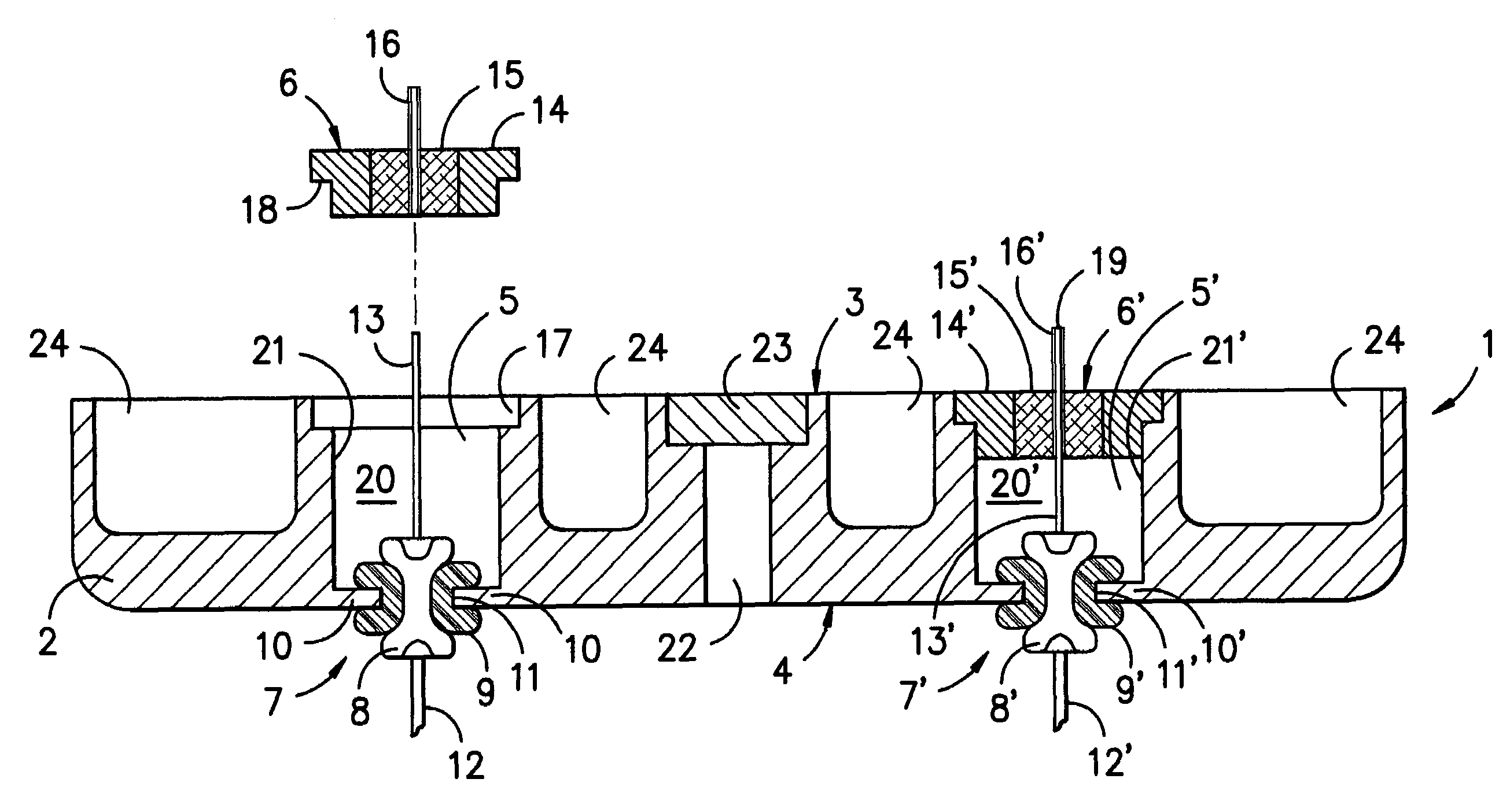
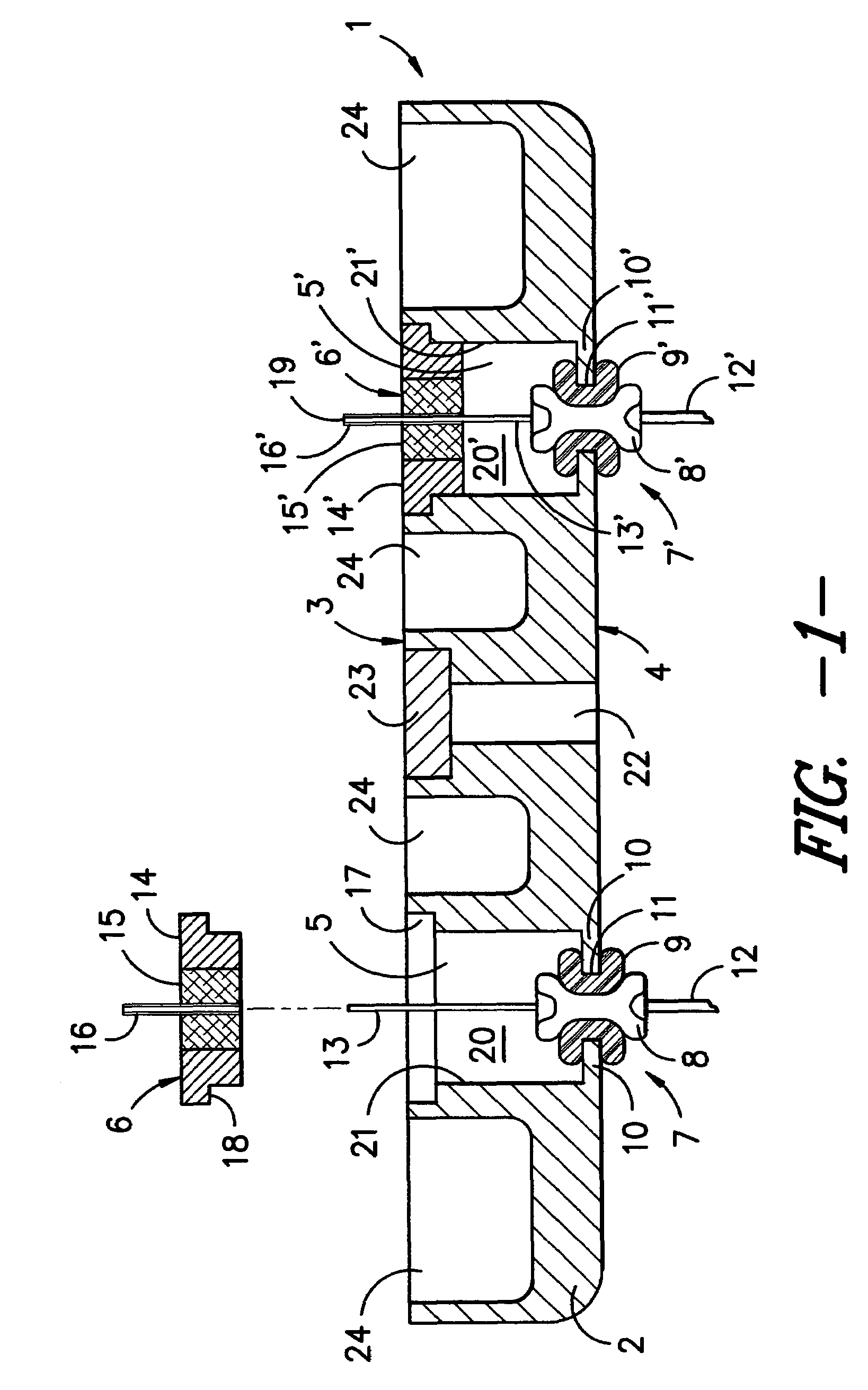
[0055]Referring to FIG. 1, lid 1 comprises metal plate 2, which is shaped to be inserted in and to seal a capacitor case. Plate 2 has an outer side3, which is part of the outer surface of the capacitor, when it is assembled, and an underside 4, which faces the interior of the capacitor and is exposed to the electrolyte solution. At least one hole 5 extends through the thickness of plate 2. Lid 1 also includes a second hole, designated as hole 5′, so that both the anode and the cathode of the capacitor may be connected through lid 1.

[0056]Hermetic seal 6 covers hole 5 adjacent the outer side 3 of plate 2, and liquid seal 7 covers hole 5 adjacent the underside 4...


PUM


Abstract

A hermetically sealed, electrolytic capacitor is provided having a lid incorporating a liquid seal on the wet side of the lid and a hermetic seal on the dry side of the lid. The lid includes a plate, with a hole through its thickness, and a flange creating an orifice in the hole, adjacent the underside of the lid. A liquid seal is positioned in the orifice and has a terminal insulated from the plate by an elastomeric ring. The terminal is electrically connected to the capacitor element on its wet side, and the terminal is electrically connected to the hermetic seal on its dry side.

Description

TECHNICAL FIELD[0001]This invention relates generally to the field of electrolytic capacitors that are hermetically sealed, and in particular to a capacitor having a liquid-tight seal between the electrolyte solution and the terminal used to make an electrical connection between the capacitor and an external device.BACKGROUND OF THE INVENTION[0002]Capacitors containing an electrolyte solution are subject to failure caused by leakage of the electrolyte liquid or vapor. For example, it is common for gas, such as hydrogen, to be evolved during operation, causing pressure to build inside the capacitor. Consequently, leaks may occur around conventional non-hermetic polymeric seals, where the terminal, for example a wire, protrudes from the capacitor housing.[0003]To avoid the leakage, a gas-tight hermetic seal is required. One prior art solution has been to provide a hermetic, outer metal-glass-inner metal seal. The “inner metal” component of the hermetic seal is typically an electricall...

Claims


Application Information

Patent Timeline
Patent Type & Authority Patents(United States)
IPC IPC(8): H01G9/10
CPCH01G9/008H01G9/10
Inventor PARLER, JR., SAMUEL G.KNIGHT, PHILIP A.
Owner CORNELL DUBILIER MARKETING
Why Eureka
Try Eureka