Converter circuit and motor driving apparatus
a converter circuit and motor technology, applied in the direction of instant pulse delivery arrangement, electric power transfer ac network, conversion with intermediate conversion to dc, etc., can solve the problems of capacitor b>17/b> not being able to reduce the size of the motor driving apparatus including these circuits, and the capacitor b>17/b> cannot be reduced by a predetermined value or more, so as to reduce the size and cost of the refrigerator, reduce the size and cost, and reduce the capacitor capacitor
- Summary
- Abstract
- Description
- Claims
- Application Information
AI Technical Summary
Benefits of technology
Problems solved by technology
Method used
Image
Examples
first embodiment
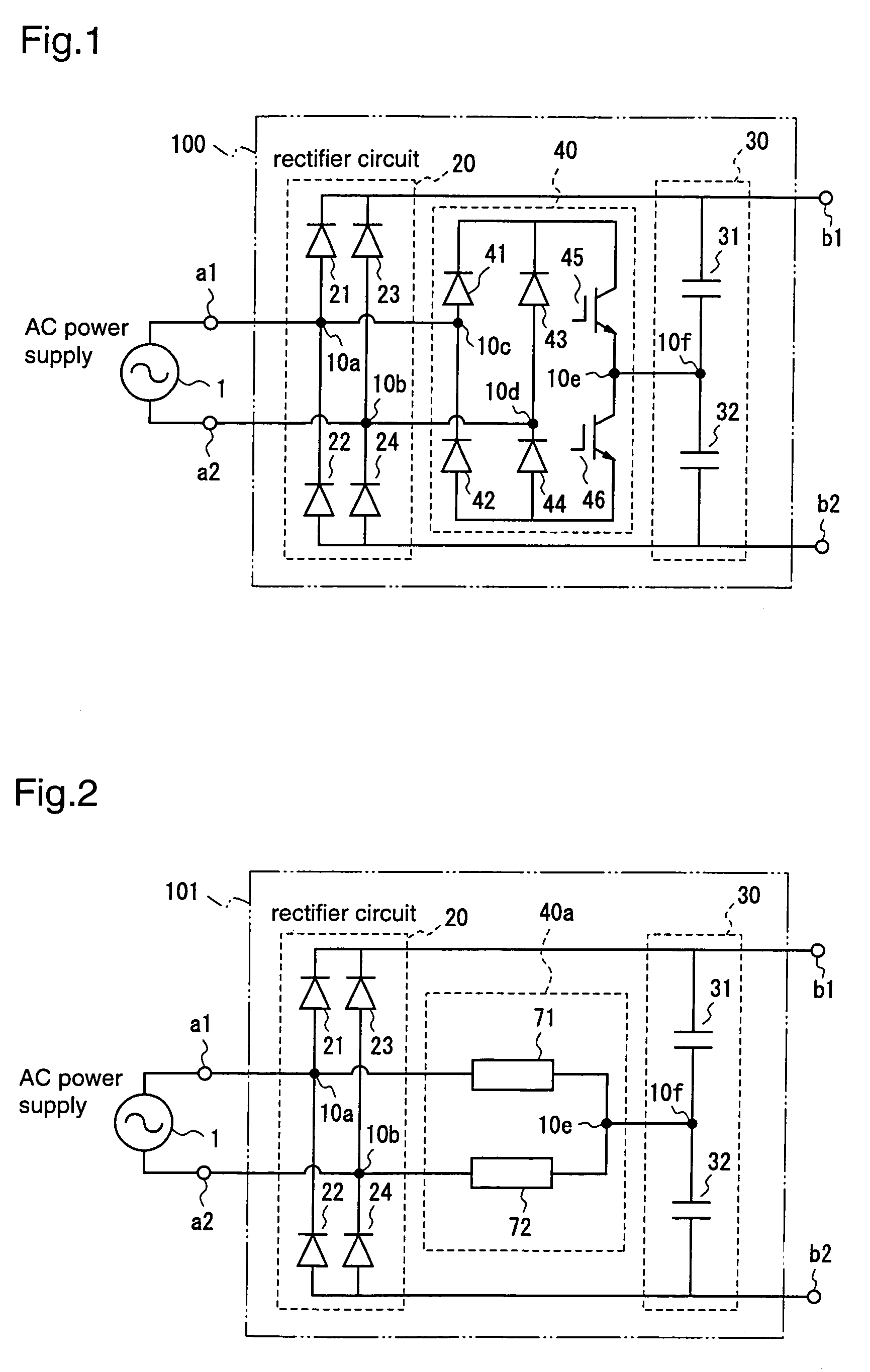
[0075]FIG. 1 is a diagram for explaining a converter circuit according to a first embodiment of the present invention.
[0076]The converter circuit 100 according to the first embodiment receives an AC voltage supplied from an AC power supply 1, and converts the input voltage into a non-negative voltage that is equal to or larger than the amplitude of the input voltage. The converter circuit 100 has a pair of input terminals a1 and a2 to which the output voltage of the AC power supply 1 is applied, and a pair of output terminals b1 and b2 from which the non-negative voltage equal to or larger than the amplitude of the input voltage is output.
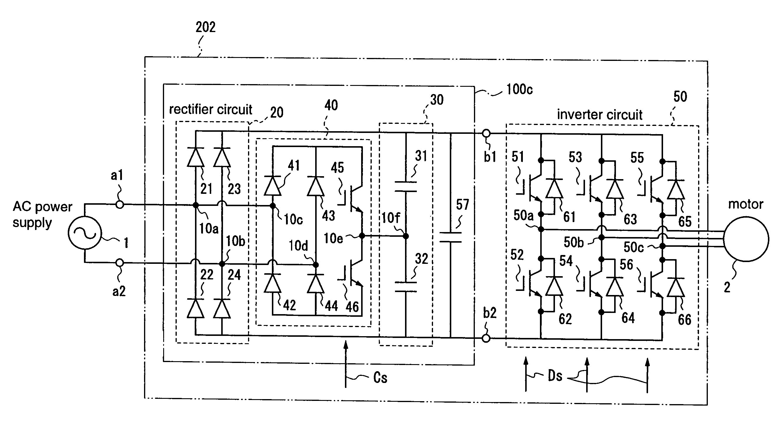
[0077]To be specific, the converter circuit 100 comprises: a rectifier circuit 20 for rectifying the output voltage of the AC power supply 1, which is applied to the input terminals a1 and a2; first and second capacitors 31 and 32 which are connected in series between the output terminals b1 and b2; and a switch circuit 40 for connecting a connecti...
second embodiment
[0100]FIG. 2 is a block diagram for explaining a converter circuit according to a second embodiment of the present invention.
[0101]The converter circuit 101 according to the second embodiment boosts the output voltage of the AC power supply 1 similar to the converter circuit 100 according to the first embodiment, and the converter circuit 101 is composed of a rectifier circuit 20, a capacitor circuit 30, and a switch circuit 40a.
[0102]The rectifier circuit 20 and the capacitor circuit 30 are identical to those of the first embodiment. The switch circuit 40a comprises a first bidirectional switching element 71 which is connected between the input terminal a1 of the converter circuit 101 and the connection node 10f of the capacitor circuit 30, and a second bidirectional switching element 72 which is connected between the input terminal a2 of the converter circuit 101 and the connection node 10f of the capacitor circuit 30.
[0103]In the switch circuit 40a, on-off of the first and secon...
third embodiment
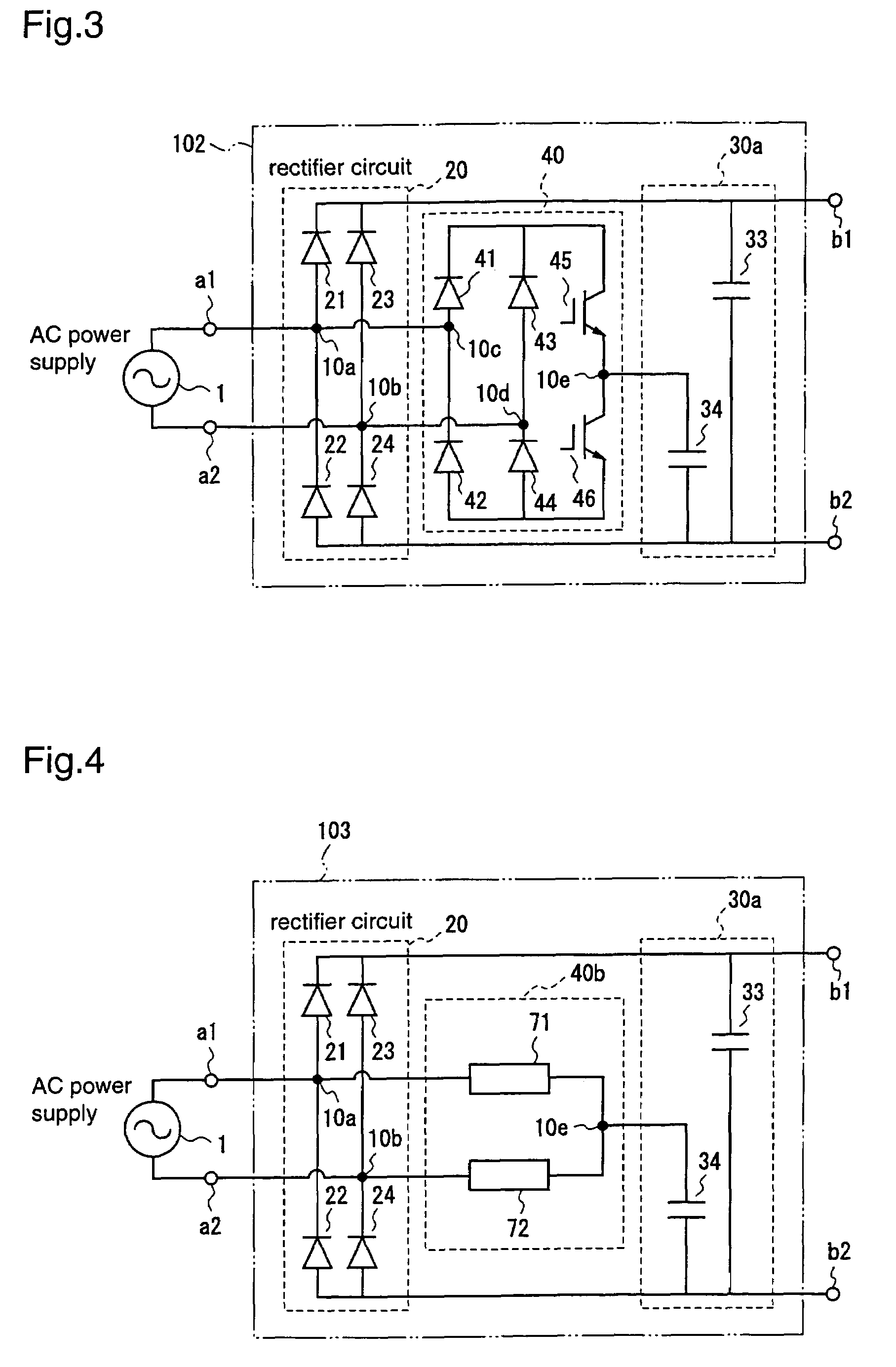
[0114]FIG. 3 is a diagram for explaining a converter circuit according to a third embodiment of the present invention.
[0115]The converter circuit 102 according to the third embodiment boosts the output voltage of the AC power supply 1 similar to the converter circuit 100 according to the first embodiment, and the converter circuit 102 is composed of a rectifier circuit 20, a capacitor circuit 30a, and a switch circuit 40.
[0116]The rectifier circuit 20 and the switch circuit 40 are identical to those of the first embodiment. The capacitor circuit 30a comprises a third capacitor 33 connected between the output terminals b1 and b2, and a fourth capacitor 34 connected between the output terminal b2 and the connection node 10e of the first and second switching elements of the switch circuit 40. While the capacitor circuit 30a comprises the two capacitors 33 and 34, the capacitor circuit 30a may comprise third and fourth capacitor units each comprising plural capacitors connected, instead...
PUM
 Abstract
Description
Claims
Application Information
 - R&D
- Intellectual Property
- Life Sciences
- Materials
- Tech Scout
- Unparalleled Data Quality
- Higher Quality Content
- 60% Fewer Hallucinations
Browse by: Latest US Patents, China's latest patents, Technical Efficacy Thesaurus, Application Domain, Technology Topic, Popular Technical Reports.
© 2025 PatSnap. All rights reserved.Legal|Privacy policy|Modern Slavery Act Transparency Statement|Sitemap|About US| Contact US: help@patsnap.com


