QoS control method for transmission data for radio transmitter and radio receiver using the method

a radio transmitter and receiver technology, applied in the field of radio transmitter/receiver, can solve the problems of increasing the delay time of data transmission, reducing the throughput, and changing the information transmission rate, so as to improve the data throughput, improve the transmission speed, and reduce the transmission delay

Inactive Publication Date: 2007-09-25
KOKUSA ELECTRIC CO LTD
View PDF9 Cites 51 Cited by
  • Summary
  • Abstract
  • Description
  • Claims
  • Application Information

AI Technical Summary

Benefits of technology

[0011]Assume that the conventional QoS control technique for the wire LAN described above is used for the radio communication system of adaptive modulation type for the radio section. The radio transmitter reads the label information added to the header or the transmission data, and classifies the transmission data according to the label information. This process of transmission data classification consumes considerable length of time, and an increased delay time of data transmission reduces the throughput.
[0013]Accordingly, an object of this invention is to provide a QoS control method and system used with a radio transmitter / receiver, in which the delay time of data transmission under QoS control is shortened and the data throughput can be improved.
[0014]Another object of the invention is to provide a radio transmitter / receiver in which the delay time of the data transmission under QoS control is shortened and the data throughput can be improved.
[0015]Still another object of the invention is to provide a radio transmitter / receiver of adaptive modulation type, in which the delay time of the data transmission under the QoS control is shortened and the data throughput is improved.
[0025]According to an embodiment of the invention, in the case where the information transmission rate for the radio section is not lower than a predetermined threshold value, the QoS control operation for the transmission data is omitted, and therefore the data transmission with minimized transmission delay in the QoS control unit is made possible for an improved data throughput. Also, the omission of the QoS control operation requiring a high speed makes possible a comparatively inexpensive hardware configuration of the radio transmitter.
[0026]According to an embodiment of the invention, the QoS control operation for the transmission data is carried out in the case where the information transmission rate for the radio section decreases below the predetermined threshold value. In this case, a time margin is generated for supplying the transmission data to the radio transmission circuit, and therefore the transmission delay due to the QoS control process has a smaller effect on the throughput. Also, the aforementioned time margin increases with the decrease in the information transmission rate for the radio section. Therefore, the QoS control operation is also made possible by a QoS control unit having a plurality of QoS control modes which are switched in accordance with the information transmission conditions in the radio section in such a manner that a more complicated QoS control operation is used with the decrease in the transmission rate.

Problems solved by technology

A system employing the adaptive modulation for radio communication poses the problem that the information transmission rate undergoes a change depending on the conditions of the radio section.
This process of transmission data classification consumes considerable length of time, and an increased delay time of data transmission reduces the throughput.
Therefore, the QoS control unit requires a high-speed processing circuit, thereby leading to the problem of a high system cost.

Method used


Image

  • QoS control method for transmission data for radio transmitter and radio receiver using the method
  • QoS control method for transmission data for radio transmitter and radio receiver using the method
  • QoS control method for transmission data for radio transmitter and radio receiver using the method

Examples


Embodiment Construction

[0048]Embodiments of the invention will be explained in detail below with reference to the accompanying drawings, in which similar component parts are designated by the same reference numerals, respectively.

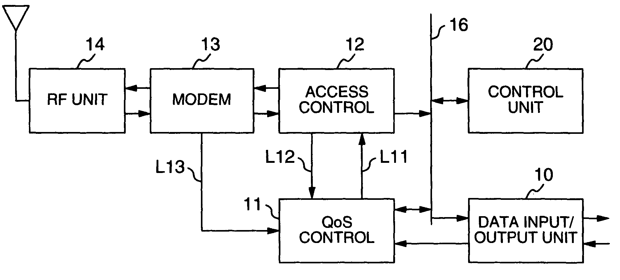
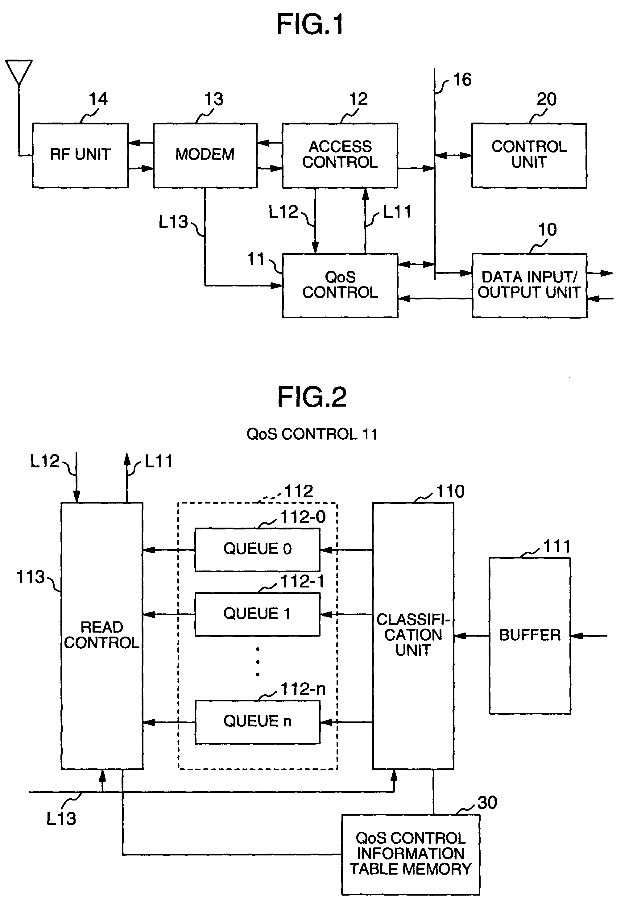
[0049]FIG. 1 is a block diagram showing a configuration of a radio transmitter / receiver according to an embodiment of the invention. The radio transmitter / receiver comprises a data input / output unit 10, a QoS control unit 11 making up the essential part of the invention, an access control unit 12 for receiving the transmission data subjected to QoS control from the QoS control unit 11, a modem 13, a RF unit 14, an antenna unit 15, an internal bus 16 and a control unit 20. The modem 13 is of adaptive modulation type with the data transmission rate variable depending on the conditions in the radio section.

[0050]The QoS control unit 11 performs the selective QoS control operation on the transmission data supplied from the data input / output unit 10, in accordance with the the radio t...


PUM


Abstract

A radio transmitter / receiver having a QoS control unit for outputting the transmission data in order taking the quality of service (QoS) into consideration. In the case where the information transmission rate for a radio section is not lower than a threshold value, the QoS control operation of the transmission data is omitted, and the transmission data are output in the order of input. In the case where the information transmission rate for the radio section is lower than the threshold value, on the other hand, the QoS control mode is switched in accordance with the information transmission rate for the radio section.

Description

BACKGROUND OF THE INVENTION[0001]The present invention relates to a radio transmitter / receiver, or in particular to the QoS (quality of service) control of the transmission data in a radio transmitter / receiver.[0002]In recent years, IP (internet protocol) has come to be employed for more and more networks with the extension of the internet and an inexpensive IP communication network. In the IP network, data are delivered to a destination from a transmitter in accordance with the IP. The IP is a protocol for a network layer (third layer) in the OSI reference model. Upper protocols include a TCP (transmission control protocol) and a UDP (user datagram protocol) in the transport (fourth) layer. The TCP and UDP have the function of acting as an intermediary between the IP and an application program. The protocols lower than IP, on the other hand, include those for a data link layer (second layer) and a physical layer (first layer). The Ethernet defined under IEEE802.3 and the radio LAN ...

Claims


Application Information

Patent Timeline
Patent Type & Authority Patents(United States)
IPC IPC(8): H04B1/38H04L5/16H04L1/00
CPCH04L1/0003H04L1/0017
Inventor NAKABAYASHI, SUMIE
Owner KOKUSA ELECTRIC CO LTD
Why Eureka
Try Eureka