
Graphical application development system for test, measurement and process control applications

a technology of application development system and graphical application development system, which is applied in the direction of memory system, program control, instruments, etc., can solve the problems of inability to modify the typical user of such programs, time-consuming and laborious development of instrumentation system software by professionals using textual programming languages such as c++, and achieve the effect of convenient saving and storag

Inactive Publication Date: 2007-09-25
MOLINARI ALFRED A +3
View PDF9 Cites 74 Cited by
  • Summary
  • Abstract
  • Description
  • Claims
  • Application Information

AI Technical Summary

Benefits of technology

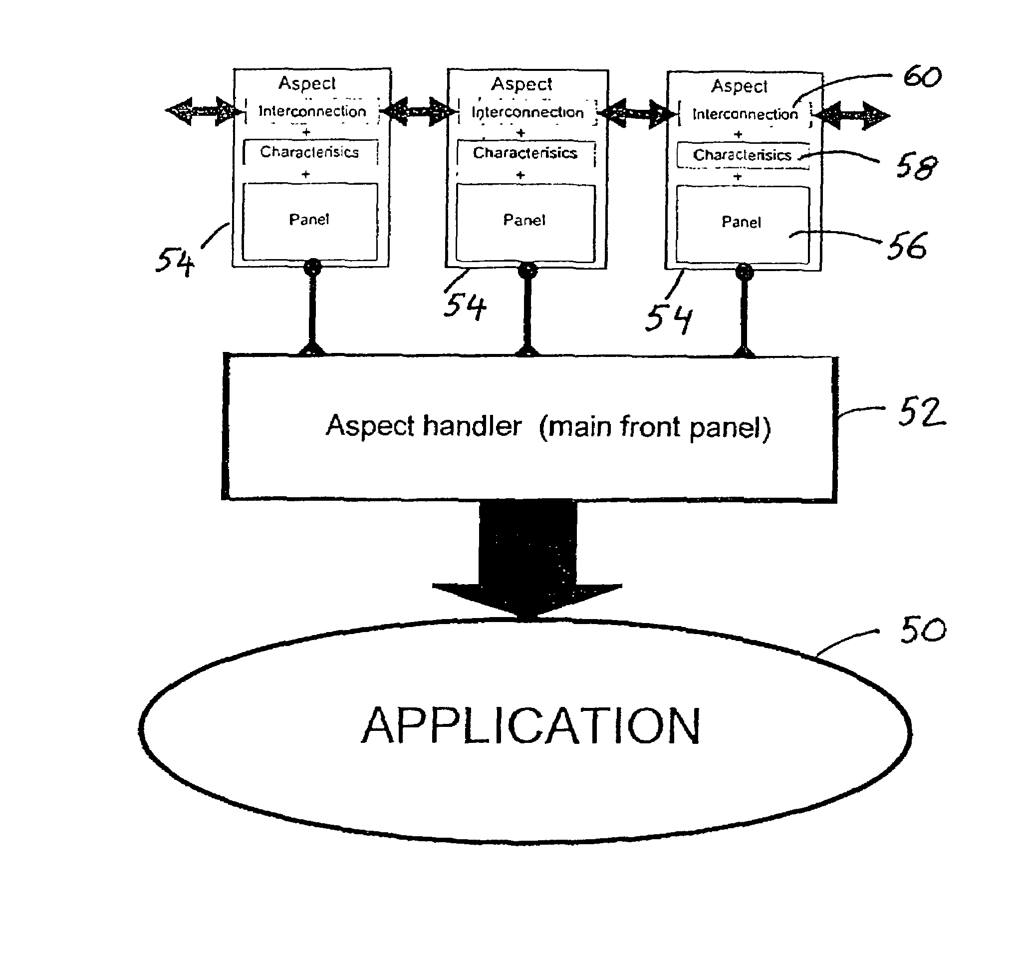
[0036]An important advantage of the present invention, and its use of “aspects” as software objects directly associated with executable code segments maintained in libraries, is that a measurement application created by a user of the invention may be fully represented in a brief text description of the chosen and configured aspects, and of their interconnections, in lieu of pages of source code. In particular, a user in creating an application program using the present invention, by using graphical tools to select and configure “panels” that represent software aspects, is simultaneously caused to create such a text file as the run time and distributable representation of the user's application. In embodiments described in the present specification, the format selected to represent and comprise user-designed programs is termed Aspect Interaction Language (AIL), an expression selected to reflect the nature of AIL as a form of program representation that is purely textual and descriptive, and that is not a programming language subject to being compiled into machine-executable code. However other textual representations of aspects descriptions and interconnections could readily be employed, for example using XML representation.

Problems solved by technology

The early development of virtual instrumentation systems faced challenging technical difficulties.
Major obstacles included the many types of electronic interfaces by which external data collection devices can be coupled to a computer, and great variety in the “command sets” used by different hardware device vendors to control their respective products.
In addition to the factors previously mentioned, the great variety in possible applications also called for professional expertise, in that one customer's measurement application was rarely suitable for a second customer: for example, one customer may have needed only to collect a single value, say outside temperature, once an hour, and to have all collected values stored in a file; the next customer possibly required that several related process temperatures, say in a rubber-curing process, be monitored continuously, and that a shut-off valve be activated in the event that the relative temperature between two process steps should vary by more than 7 degrees for a time period of 3 seconds or more, in any 15 minute period, and to store only data concerning such episodes.
The development of instrumentation systems software by professionals using textual programming languages such as C++ is very time consuming and tedious, and it typically results in the production of a program consisting of many pages of so-called source code, written in a computer language that is virtually unreadable by non-programmers, and which thus cannot be modified by the typical users of such programs.
User-designed systems developed using these prior art graphical development systems are also prone to errors, because they generally allow the use unwittingly to wire together components that are functionally incompatible.
The known prior art systems lack built-in safeguards against the construction of unworkable combinations of components, and provide inadequate intuitive guidance to the user seeking to develop a measurement application.

Method used


Image

  • Graphical application development system for test, measurement and process control applications
  • Graphical application development system for test, measurement and process control applications
  • Graphical application development system for test, measurement and process control applications

Examples


Embodiment Construction

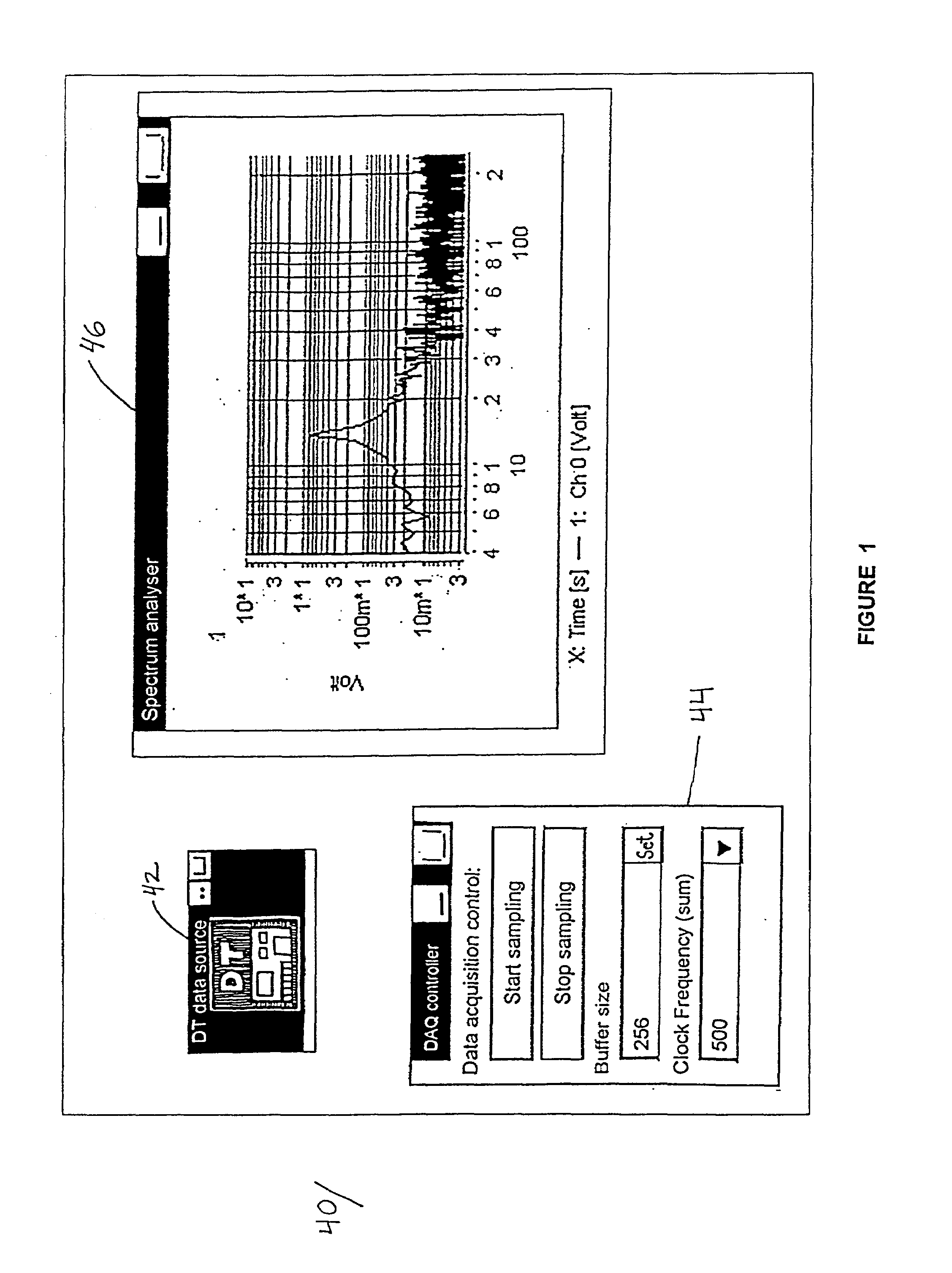
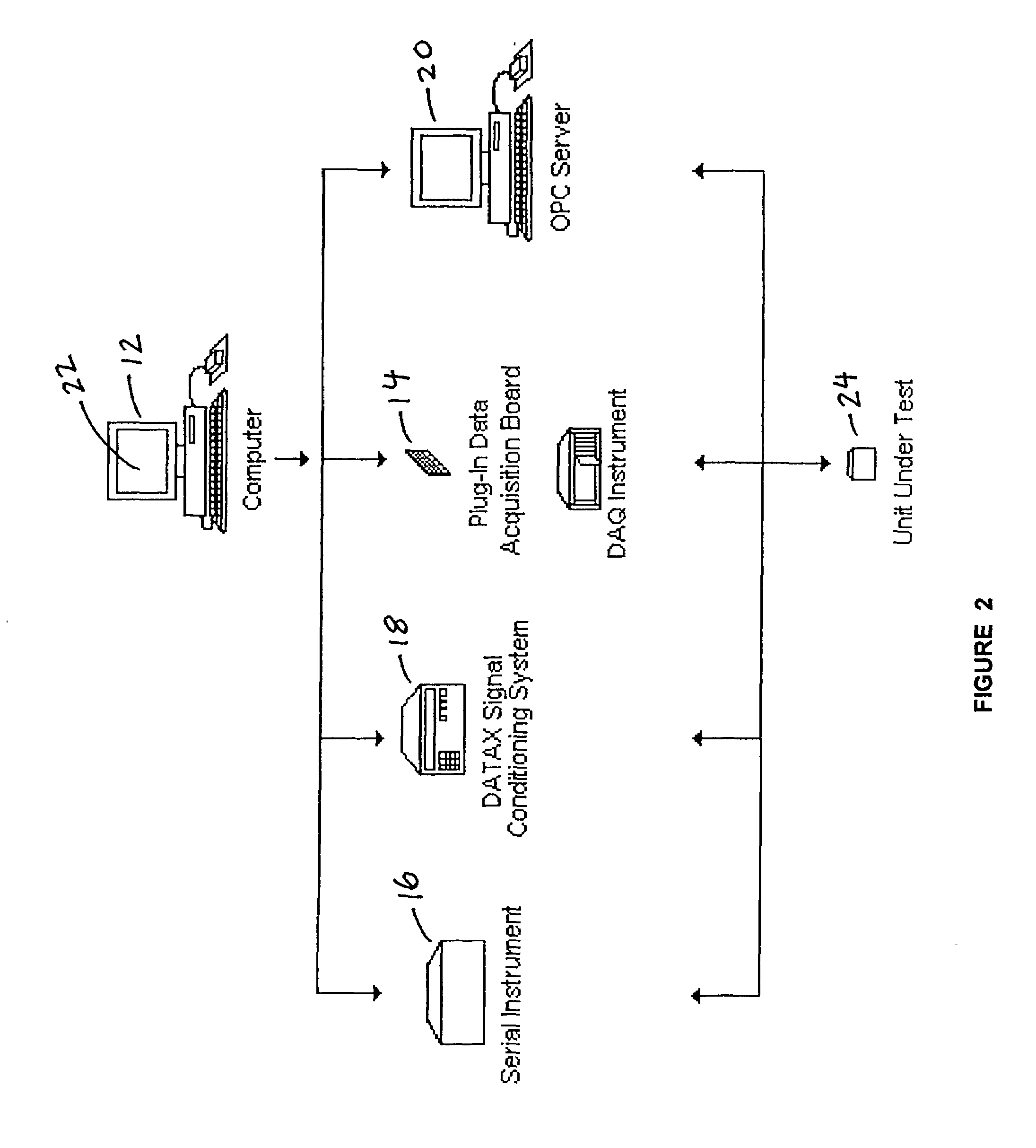
[0073]The system of the present invention comprises software that provides users with a graphical development environment that is specifically adapted for the development of customized measurement environments. The graphical application development software of the present invention has been designed to be run on a conventional personal computer, preferably a computer equipped with an operating system, such as the Windows series of Microsoft operating systems, that is adapted to supervise graphical applications. The embodiments of the invention as described in this specification may of course be employed on any other type of computer capable of running conventional Windows applications, and embodiments of the invention based on the present description may also readily be developed for other computer platforms, in a manner known to persons skilled in the art.

[0074]It is a principal object of the present invention to provide a user, equipped with a computer such as a personal computer,...


PUM


Abstract

A graphical application development environment is provided, for the development of test, measurement and process control applications. Said environment comprises thematically organized groups of “panels” representing components of virtual instruments, and said panels are combined and interconnected via data channels, control channels and event channels to form a complete instrument “front panel.” Each panel represents a quasi-autonomous “aspect” software object that has the attributes, properties and connectivities of the represented instrument component, and that is associated with executable code segments, including code segments that are usable by a plurality of aspects and are maintained in libraries accessible to an aspect handler for the construction of aspects. A representation of a user-developed application program, as created in a textual language, comprises an executable description of front panel aspects and their attributes and interconnections, and serves to invoke said associated code segments to run said user application.

Description

[0001]The present application incorporates previously filed Provisional Application for Patent Ser. No. 60 / 315,830 filed Aug. 29, 2001.FIELD OF THE INVENTION[0002]The present invention relates to computerized systems for developing virtual instrumentation systems, and more particularly to graphical development software and systems for the design and construction of virtual instrumentation systems including test and measurement applications.BACKGROUND[0003]The present invention concerns computer software that is used to create and operate “virtual instrumentation systems.” That is, the invention concerns computer software that a user would employ to develop a computerized test and measurement system, for controlling from a computer desktop an external measurement hardware device and for displaying, on instrument-like panels on a computer screen, test or measurement data collected by the external device. The invention extends also to computerized systems for controlling processes base...

Claims


Application Information

Patent Timeline
IPC IPC(8): G06F9/44G01R13/34
CPCG01R13/345
Inventor MOLINARI, ALFRED A.RANDOW, ANDREAS CLAUSSCHMISCHKE, DIRK RICKGABLER, FRANK
Owner MOLINARI ALFRED A
Learn More