Exhaust pressure-raising device for an internal combustion engine

a technology of exhaust pressure raising and internal combustion engine, which is applied in the direction of machines/engines, braking systems, couplings, etc., can solve the problems of reducing the efficiency of fuel consumption, deteriorating combustion quality, and high cost, and achieves the improvement of exhaust emission quality and combustion stability or fuel consumption efficiency, simple construction, and low cost

Inactive Publication Date: 2007-10-02
MITSUBISHI MOTORS CORP
View PDF12 Cites 22 Cited by
  • Summary
  • Abstract
  • Description
  • Claims
  • Application Information

AI Technical Summary

Benefits of technology

[0015]The present invention has been made to resolve the above problems. The present invention provides an exhaust pressure-raising device for an internal combustion engine capable of achieving both an effect of improving an exhaust emission quality and combustion stability or fuel consumption efficiency at the same time with a simple construction at low cost.
[0016]To accomplish this, the exhaust pressure-raising device for an internal combustion engine according to the present invention comprises a throttle valve that is disposed in an exhaust channel of an internal combustion engine and is closed to reduce channel area of the exhaust channel and raise exhaust pressure in the exhaust channel, and an exhaust pressure-adjusting valve that is brought into a closed position due to a biasing force of a resilient body and is opened against the biasing force of the resilient body due to the exhaust pressure in the exhaust channel, which is raised in response to the closing of the throttle valve, in which valve-opening area is increased or decreased according to displacement of the resilient body, to thereby adjust the raised exhaust pressure, the device in which the exhaust pressure-adjusting valve has means for changing the growth rate of the valve-opening area, which alters the growth rate of the valve-opening area with respect to the displacement of the resilient body in a valve-opening direction.

Problems solved by technology

Too high exhaust pressure, however, incurs deterioration in the combustion quality, attributable to an increase in the internal EGR and the like, and a decrease in fuel consumption efficiency, attributable to an increase in exhaust resistance.
Moreover, being an exhaust component, the relief valve is required to have high heat resistance, which entails high cost.
Consequently, in case that a resilient body is used, the materials of the resilient body uniquely determines the relation of the exhaust flow rate and the valve-opening area, which produces the problem that the degree of freedom thereof is low and that the prescribed characteristics that meets the above requirements cannot be fully obtained.

Method used


Image

  • Exhaust pressure-raising device for an internal combustion engine
  • Exhaust pressure-raising device for an internal combustion engine
  • Exhaust pressure-raising device for an internal combustion engine

Examples


first embodiment

[0028]Firstly, a first embodiment will be explained.

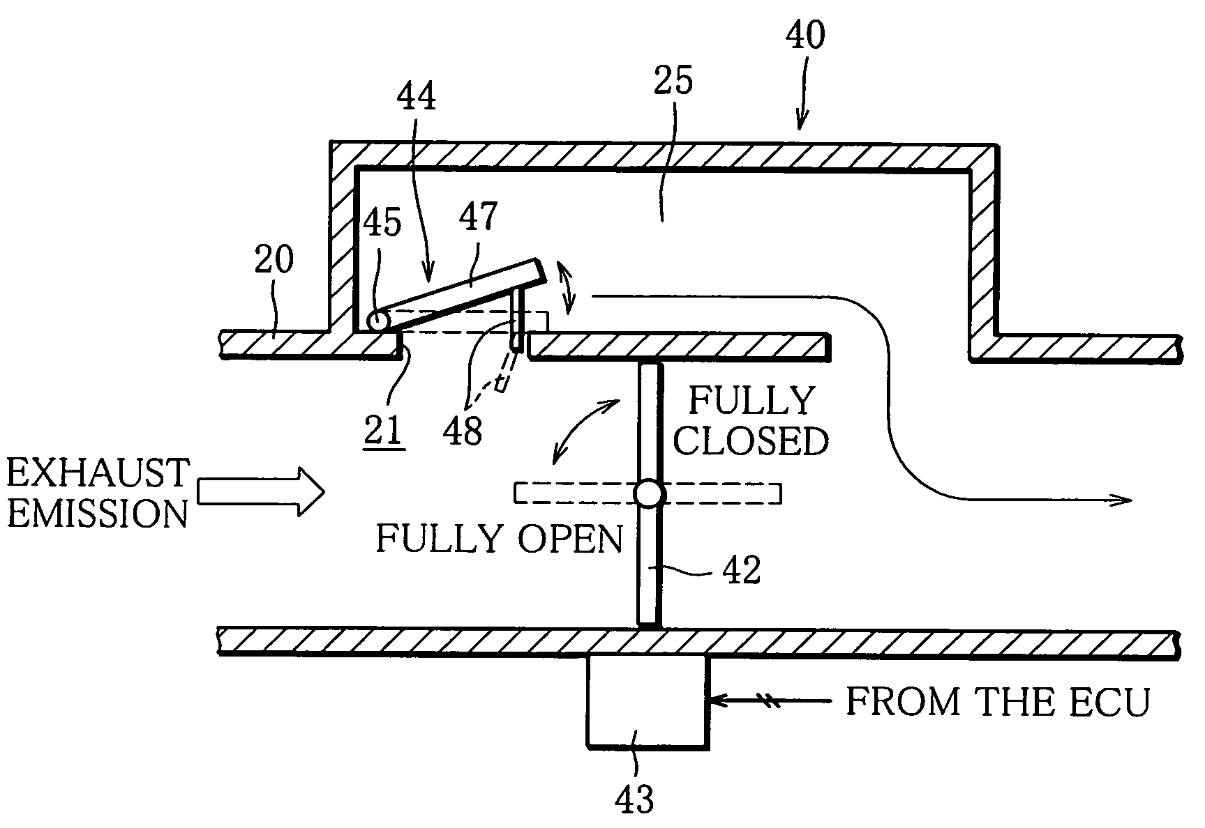
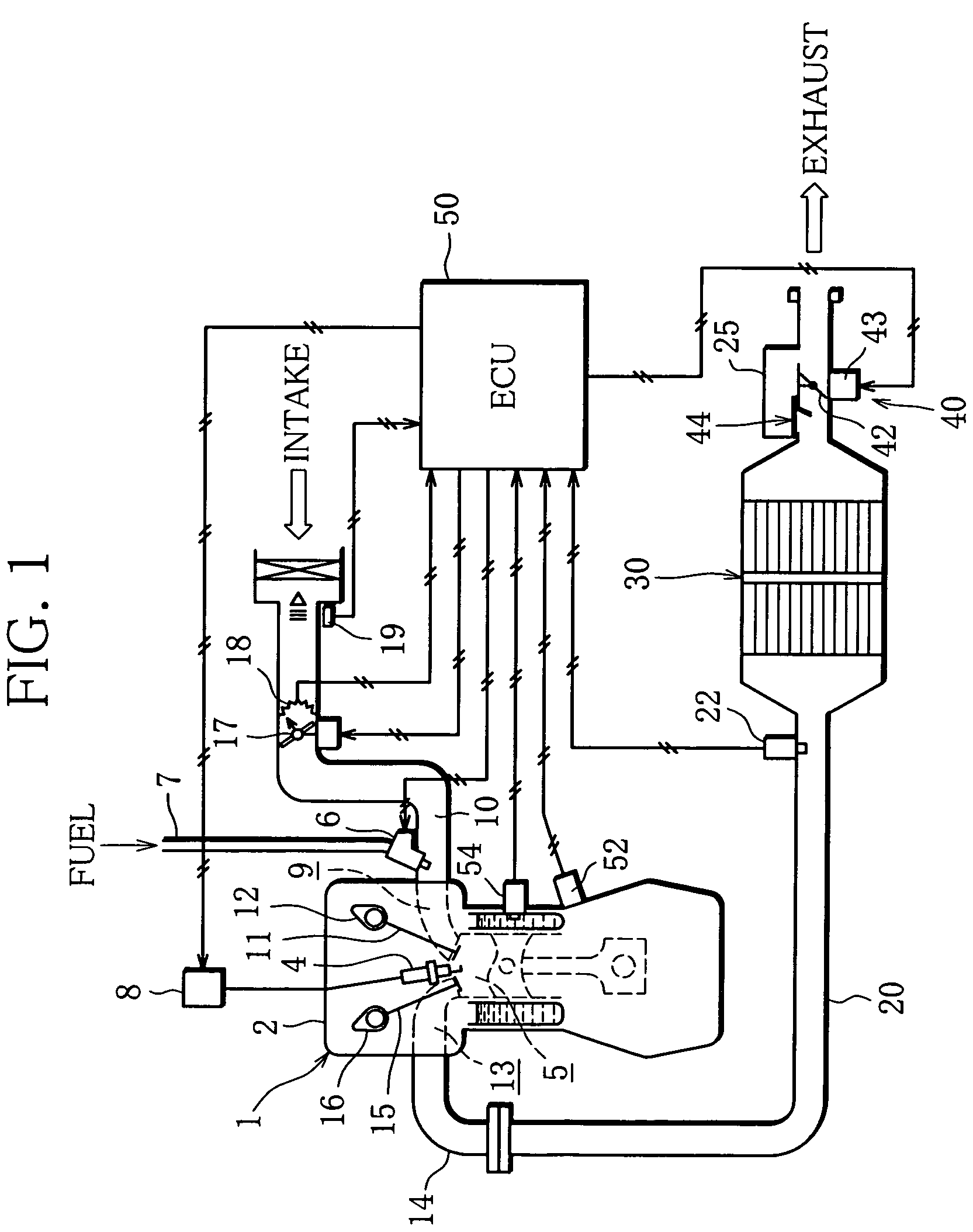
[0029]FIG. 1 schematically shows a system construction of an internal combustion engine including an exhaust pressure-raising device according to the present invention, which is installed in a vehicle.

[0030]As illustrated in FIG. 1, an intake-manifold injection (multipoint injection: MPI) type gasoline engine is employed as an engine body (hereinafter referred to as engine) 1 functioning as an internal combustion engine.

[0031]In a cylinder head 2 of the engine 1, an ignition plug 4 is attached to each cylinder, and an ignition coil 8 for outputting high voltage is connected to the ignition plug 4.

[0032]In the cylinder head 2, an intake port 9 is provided to each cylinder. An intake valve 11 is formed in each intake port 9 at an end close to a combustion chamber 5, the intake valve 11 being operated to open and close along with a cam of a cam shaft 12 that rotates according to engine revolution and makes the intake port 9 communicat...

second embodiment

[0063]Next, a second embodiment will be explained below.

[0064]A difference between the second embodiment and the first, in terms of the exhaust pressure-adjusting valve 44, is the attaching position of the shield. Hereinafter, the explanation about the parts identical to those of the first embodiment will be omitted, and the parts different from those of the first embodiment will be described.

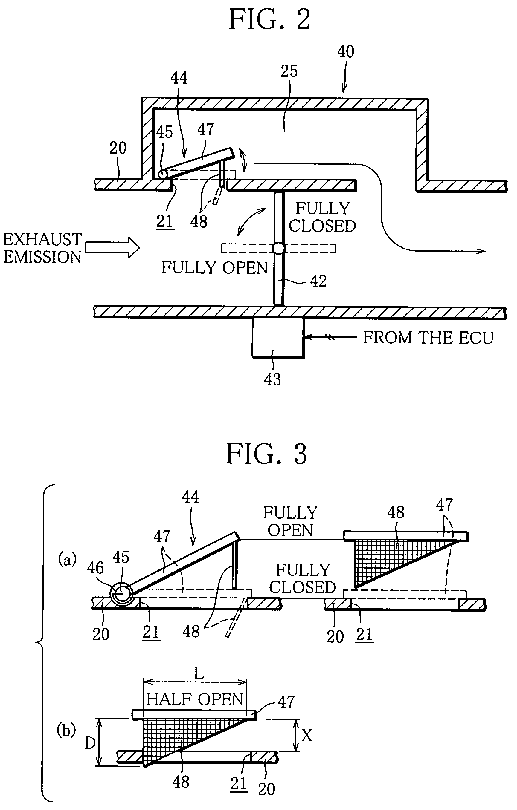
[0065]FIG. 5 is a detail view of an exhaust pressure-adjusting valve 44′ according to the second embodiment, showing a fully open position (a) and a half-open position (b). The details about the exhaust pressure-adjusting valve 44′ according to the second embodiment will be described below with reference to FIG. 5.

[0066]As illustrated in FIG. 5, in the exhaust pressure-adjusting valve 44′, a shield 48′ is disposed upright not in the end of the valve element 47 but in the outer circumferential surface of the exhaust pipe 20 to be positioned downstream of the exhaust flow from the opening hole 21...

third embodiment

[0070]Next, a third embodiment will be described below.

[0071]The third embodiment is different in that the shield 48′ of the exhaust pressure-adjusting valve 44′ of the second embodiment is improved. The explanation about the parts identical to those of the first and second embodiments will be omitted, and only the parts different from those of the second embodiment will be described.

[0072]FIG. 6 is a detail view of an exhaust pressure-adjusting valve 44″ according to the third embodiment, showing a fully open position (a) and a half-open position (b). Hereinafter, the detail about the exhaust pressure-adjusting valve 44″ according to the third embodiment will be explained with reference to FIG. 6.

[0073]As illustrated in FIG. 6, in the exhaust pressure-adjusting valve 44″, a shield 48″ is disposed upright in the outer circumferential surface of the exhaust pipe 20 to be positioned downstream of the exhaust flow from the opening hole 21 to sit at the circumferential edge of the openi...


PUM


Abstract

There is provided an exhaust pressure-adjusting valve that is brought into a closed position due to a biasing force of a resilient body and is opened against the biasing force of the resilient body due to the exhaust pressure in an exhaust channel, which is raised in response to the closing of a throttle valve, in which valve-opening area is increased or decreased according to the displacement of the resilient body, to thereby adjust the exhaust pressure. The exhaust pressure-adjusting valve has a unit for changing the growth rate of the valve-opening area, which gradually heightens the growth rate of the valve-opening area with respect to the displacement of the resilient body in a valve-opening direction.

Description

CROSS-REFERENCE TO THE RELATED ART[0001]This application incorporates by reference the subject matter of Application No. 2003-427421, filed in Japan on Dec. 24, 2003, on which a priority claim is based under 35 U.S.C. §119(a).BACKGROUND OF THE INVENTION[0002]1. Field of the Invention[0003]The present invention relates to an exhaust pressure-raising device for an internal combustion engine, and more specifically to a technology for achieving both the effect of improving the exhaust emission quality and the combustion stability or the fuel consumption efficiency at the same time.[0004]2. Description of the Related Art[0005]It is known that if exhaust pressure in an exhaust system (from a combustion chamber to an exhaust pipe) is raised by using an exhaust pressure-raising device comprising, for example, an exhaust throttle valve, a reaction of unburnt materials (HC, CO and the like) and oxygen is promoted in the exhaust system, which makes realizable a reduction in emissions of hazard...

Claims


Application Information

Patent Timeline
Patent Type & Authority Patents(United States)
IPC IPC(8): F01N7/00F01N3/20F01N13/08F02D9/04F02D9/06F02D9/10F02D9/18F02M25/07
CPCF01N3/2006F02D9/04F02D9/06F02D9/103F02D9/1045F02D9/18F02M25/0752F02D9/104F02D9/102Y02T10/26F02D9/1055Y02T10/121F02M26/01Y02T10/12Y10T137/87265Y10T137/87338Y10T137/87378
Inventor TAMURA, YASUKISUZUKI, MOTOYUKI
Owner MITSUBISHI MOTORS CORP
Why Eureka
Try Eureka