[0006]It is an object of the present invention to provide a power transmission device that is simple in structure as well as small in size.
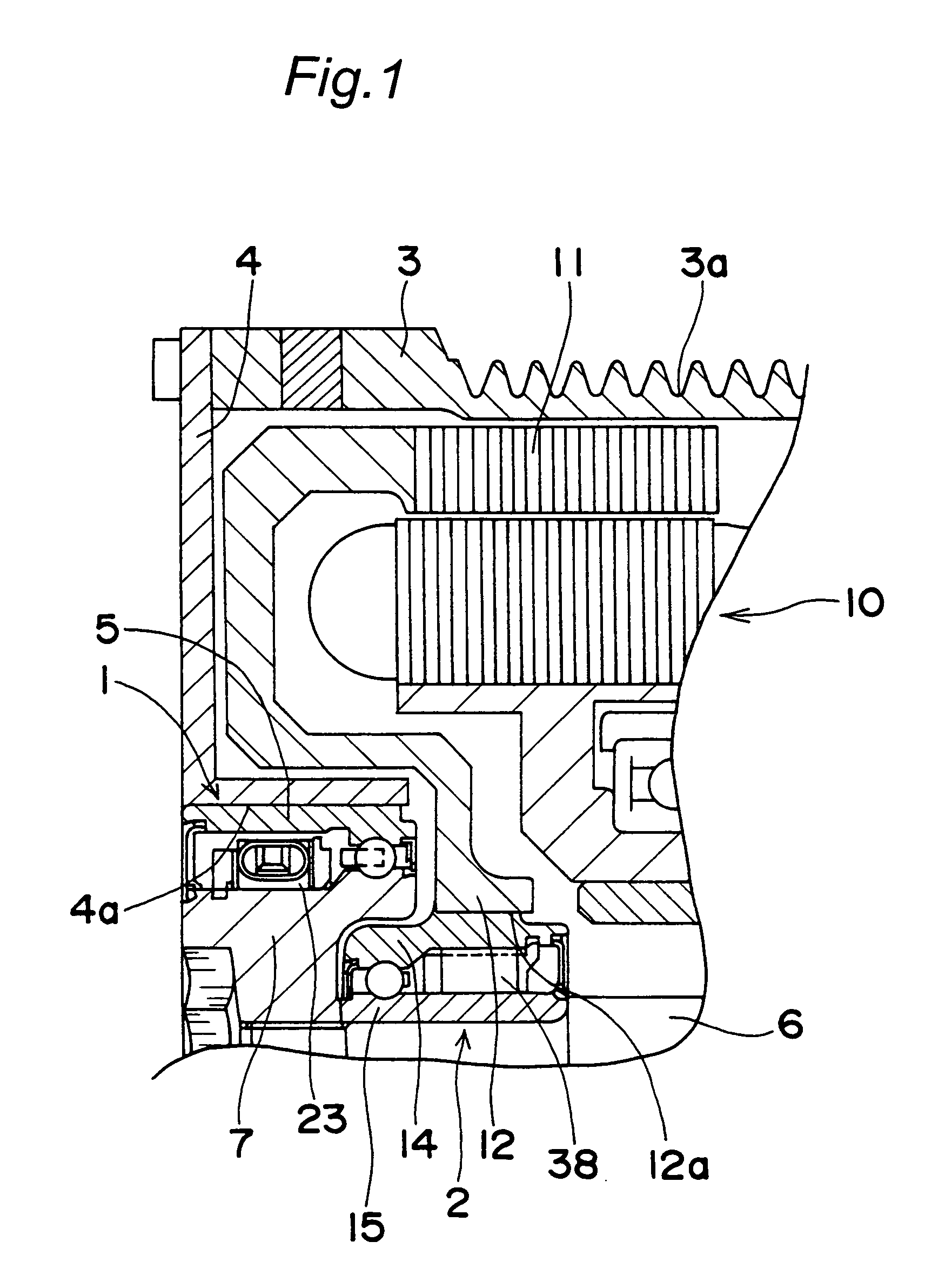
[0017]Suppose, for example, that, in the power transmission device with the above construction, the outer ring of the first one-way clutch is connected to the pulley driven by an engine, that the outer ring of the second one-way clutch is connected to the rotor of the motor, and that the inner ring of the first one-way clutch and the inner ring of the second one-way clutch are connected to a rotating shaft of a compressor. Then, while the engine is operating, the rotational power of the pulley driven by the engine is transmitted to the rotating shaft of the compressor via the outer ring, engagement members and inner ring of the first one-way clutch, so that the rotating shaft of the compressor is rotated by the engine. During the operation of the engine, the second one-way clutch is in a disengaged state, and the inner ring of the second one-way clutch freely rotates. On the other hand, while the engine is not operating, the motor is driven so that a rotational power of the rotor of the motor is transmitted to the rotating shaft of the compressor via the outer ring, engagement members and inner ring of the second one-way clutch, whereby the rotating shaft of the compressor is rotated by the motor. While the engine is not operating, the first one-way clutch is in a disengaged state, and the inner ring of the first one-way clutch freely rotates or idles. In this way, the power transmission device is able to drive the rotating shaft of the compressor by the first and second one-way clutches both while the engine is operating and while the engine is not operating. Therefore, no electromagnetic clutch or control part therefor is required. This enables the power transmission device to be simple in structure and compact.
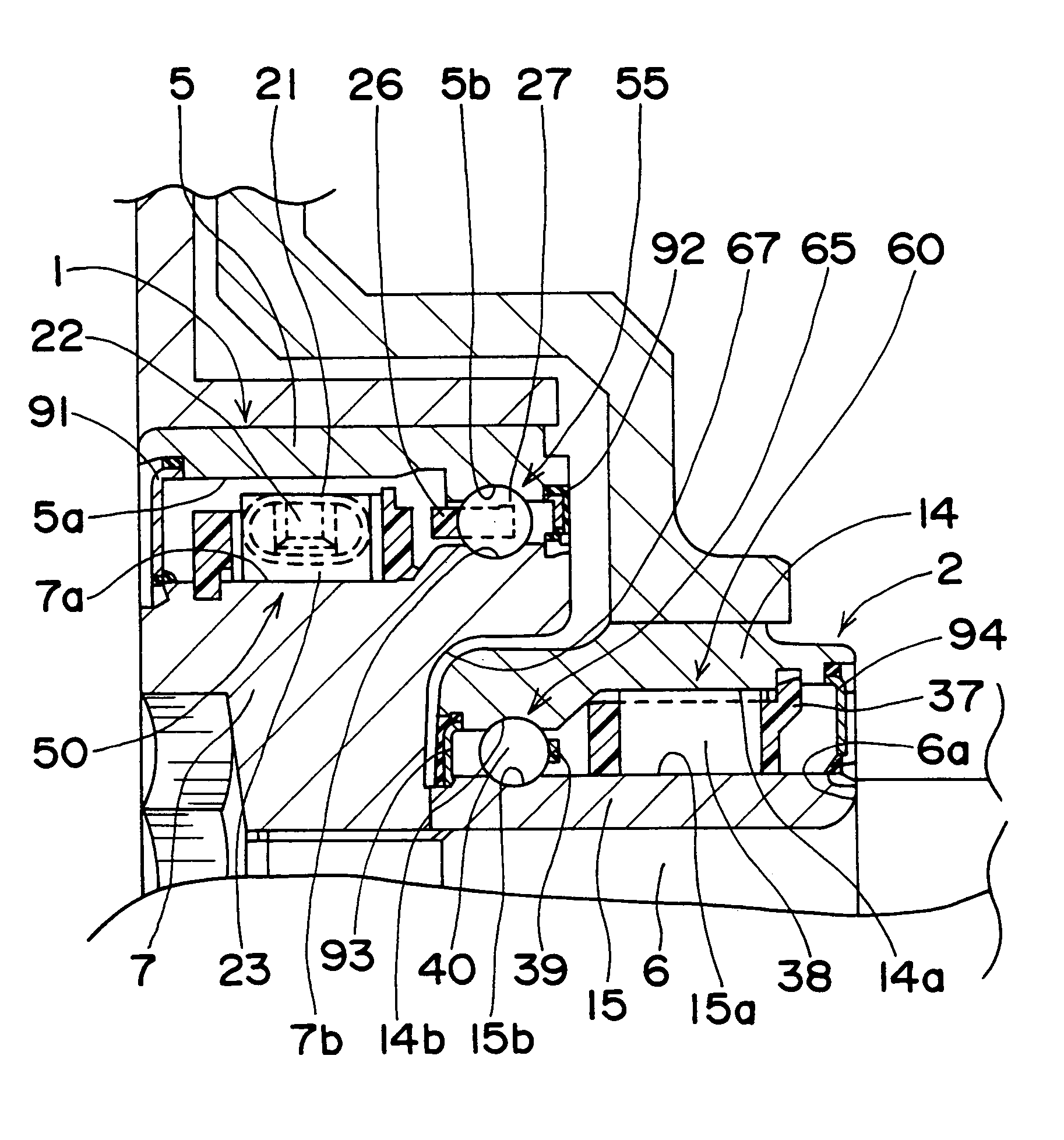
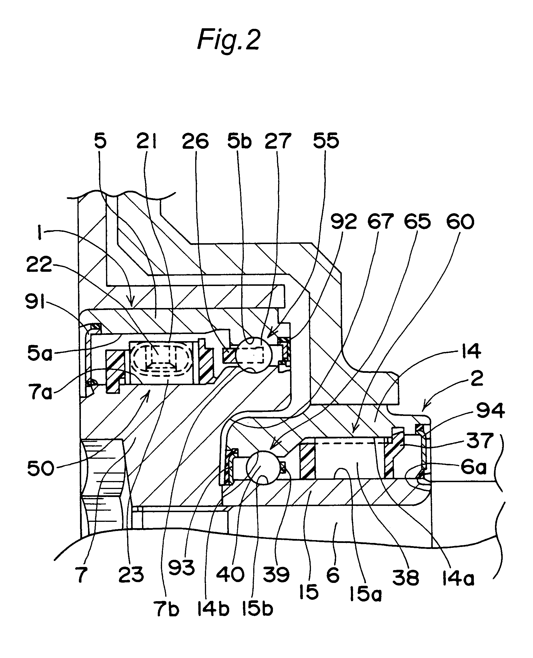
[0018]According to an example embodiment of the power transmission device, the second one-way clutch is made as a so-called outer cam type one-way clutch in which the engagement cam-surface is formed at the inner periphery of the outer ring and the engagement cylindrical surface is formed at the outer periphery of the inner ring. Thus, a
radius of the engagement cylindrical surface of the second one-way clutch is reduced, as compared with the case where the second one-way clutch is made as a so-called inner cam type one-way clutch in which the engagement cam-surface is formed at the outer periphery of the inner ring, and the engagement cylindrical surface is formed at the inner periphery of the outer ring. That is, when the second one-way clutch is in a disengaged state, and the engagement rollers are thus in an idling state, a relative circumferential speed between the engagement cylindrical surface of the second one-way clutch and the engagement rollers, which speed is proportional to the above-mentioned
radius, can be reduced by decreasing the
radius. During the time in which the engine is operating, in most of which time the rotational speed of the pulley is relatively higher than that of the rotating shaft, the engagement rollers are in a sliding state on the engagement cylindrical surface. Therefore, reducing the relative circumferential speed of the engagement cylindrical surface of the second one-way clutch with respect to the engagement rollers, as mentioned above, contributes to the reduction of the heat release value due to friction between the engagement cylindrical surface and the engagement rollers. Consequently, the lifetime of
grease sealed in between the outer ring and inner ring of the second one-way clutch can be prolonged.
[0023]According to the power transmission device of this embodiment, because in at least one of the first one-way clutch and the second one-way clutch, the inner ring and the outer ring are provided with raceway surfaces adjacent the engagement surfaces of the inner ring and the outer ring and balls are disposed between these raceway surfaces so that a
ball bearing portion is provided, the
ball bearing portion can support radial loads applied to the one-way clutch provided with the
ball bearing portion. Accordingly,
load resistance and durability of the one-way clutch provided with the ball bearing portion are favorably maintained.

