Thin-wall polytetrafluoroethylene tube

a polytetrafluoroethylene tube and thin-wall technology, applied in the direction of dilators, prostheses, synthetic resin layered products, etc., can solve the problems of little memory, back to its full diameter does not retain creases and wrinkles, etc., to achieve effective repair of living blood vessels, good hoop strength, and add significant longitudinal strength of tubes

Inactive Publication Date: 2007-10-09
GORE ENTERPRISE HLDG INC
View PDF95 Cites 79 Cited by
  • Summary
  • Abstract
  • Description
  • Claims
  • Application Information

AI Technical Summary

Benefits of technology

[0010]The inventive thin-wall PTFE tube has good hoop strength because of the circumferentially oriented layers of film. The tube is flexible and collapsible, thereby allowing it to be collapsed to a size much smaller than the full inside diameter. It has very little memory, so that such a tube that was previously collapsed and subsequently brought back to its full diameter does not retain the creases and wrinkles of its collapsed state. The thin-wall PTFE tube is therefore particularly useful as an intraluminal graft. Such a graft is capable of being implanted into a living body in the collapsed state and can therefore be inserted into a conveniently accessible, smaller diameter portion of a body conduit and then transferred to another, larger diameter portion of the body conduit where it is needed with the use of a catheter type of delivery system. One end of the intraluminal graft is then secured by suitable means such as the use of one or more metallic expandable stents. The use of the inventive intraluminal graft thus allows for the effective repair of living blood vessels without the trauma typically associated with conventional invasive vascular surgery.
[0011]The inventive tube may optionally incorporate separate longitudinally-oriented ribs intended to serve as additional strength members. These ribs may be in the form of, for example, stringers of PTFE or fluorinated ethylene propylene (hereinafter FEP) of small diameter such as about 0.025 mm to about 0.5 mm. The use of such longitudinally-oriented ribs can add significantly to the longitudinal strength of the tube without appreciably interfering with the ability of the tube to be collapsed in diameter for ease of insertion into a vascular system and then subsequently increased in diameter at a different location within the vascular system. These ribs may easily be incorporated into the tube during construction by temporarily attaching the ribs to the surface of a manufacturing mandrel prior to wrapping the mandrel with a layer of porous expanded PTFE film. The mandrel assembly can then be heated adequately to cause the ribs to adhere to the film, after which the mandrel can be removed. The ribs may be located on the luminal surface of the film, on the exterior surface of the film, or between two layers of the film.

Problems solved by technology

It has very little memory, so that such a tube that was previously collapsed and subsequently brought back to its full diameter does not retain the creases and wrinkles of its collapsed state.

Method used


Image

  • Thin-wall polytetrafluoroethylene tube
  • Thin-wall polytetrafluoroethylene tube
  • Thin-wall polytetrafluoroethylene tube

Examples


example 1

[0071]A thin-wall tube was constructed by wrapping porous expanded PTFE film about an 8 mm diameter cylindrical stainless steel mandrel and then heating the film-wrapped mandrel. A 60 cm length of porous expanded PTFE film was wrapped around the surface of the mandrel with the fibrils of the film oriented parallel to the longitudinal axis of the mandrel. The film used was of about 0.03 mm thickness, 40 mm width, 40 micron fibril length, and about 0.3 g / cc density. The density of non-porous PTFE is about 2.2 g / cc; consequently the chosen film was about 86% porous. All film thickness measurements for each example were made with a Mitutoyo model no. 2804-10 snap gauge having a part no. 7300 frame, by placing a film sample between the measuring pads of the gauge and gently easing the pads into contact with the film sample until the pads were in full contact with the film sample under the full force of the spring-driven snap gauge. Film density values were based on the bulk volume of a f...

example 2

[0075]A bifurcated thin-wall tube was made by first constructing a flat mandrel 71 from 1.5 mm thick stainless steel as shown by FIG. 7; the mandrel 71 was cut into a Y-configuration wherein the trunk 73 was about 18 mm wide and legs 75 of the mandrel 71 were about 10 mm wide; the trunk 73 and legs 75 were each of about 80 mm length; the centerline 76 of each leg 75 diverged from the centerline 74 of the trunk 73 by an angle of about 15 degrees. The legs 75 were made as separate pieces and were retained to the trunk 73 in a removable fashion by the use of pins 77. All edges of the mandrel 71 were radiused.

[0076]The completed mandrel was placed between 2 layers of the same film used previously for the longitudinally-oriented film of Example 1. The fibrils of the layers of film were oriented parallel to the longitudinal axis of the trunk of the mandrel. The edges of the film were sealed together and trimmed around the perimeter of the flat mandrel in the same fashion as the edge of th...

example 3

[0085]A thin-wall tube of the type described in Example 1 was constructed of a discontinuous FEP-coated film. Examination of the FEP-coated side of the film by scanning electron microscopy revealed FEP on only small portions of the nodes and fibrils at the surface of the film. It was estimated that less than 10% of the available node and fibril surface area exposed at the surface of the film was covered by FEP. The presence of the FEP adhesive thus had little or no adverse effect on the porosity of the porous PTFE layer of the film. This FEP-coated film was about 0.01 mm thick, of about 50 micron fibril length and had a density of about 0.3 g / cc.

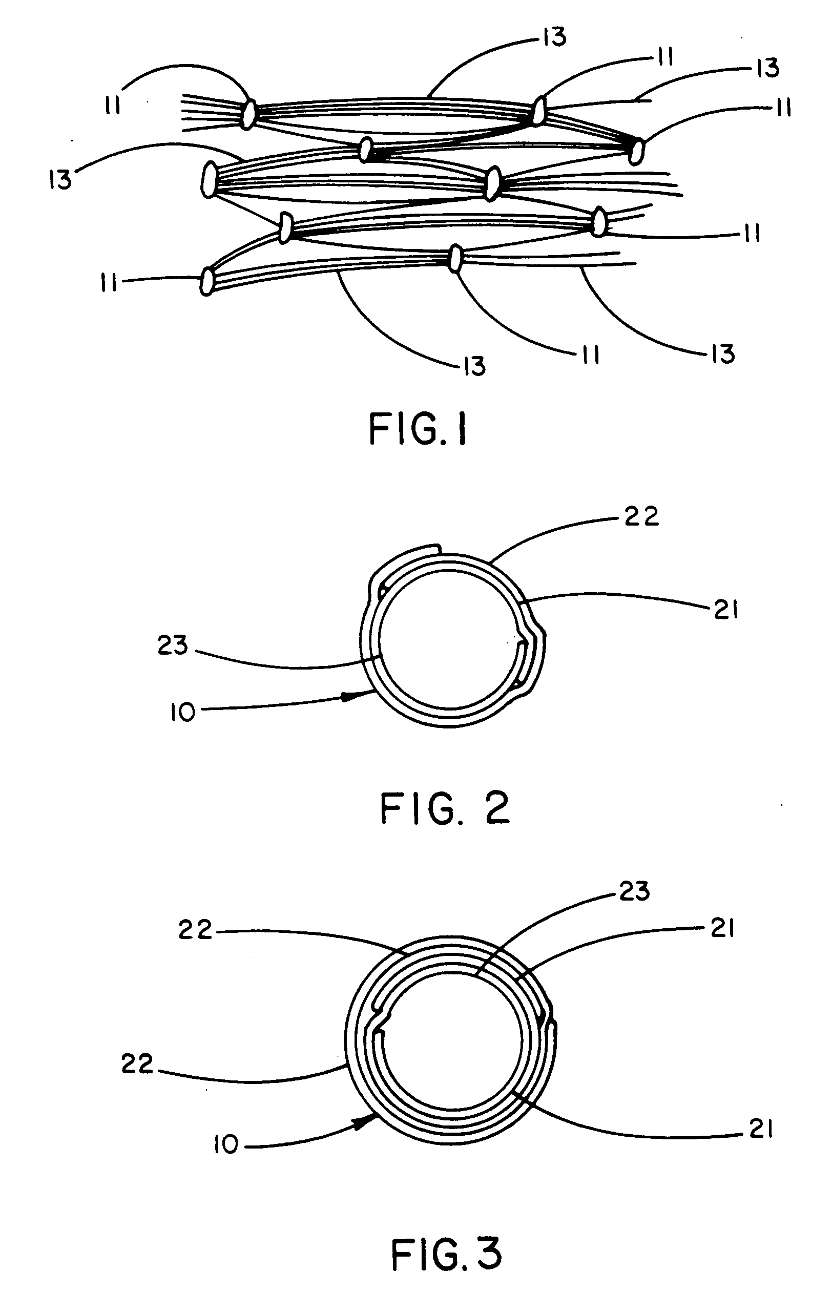
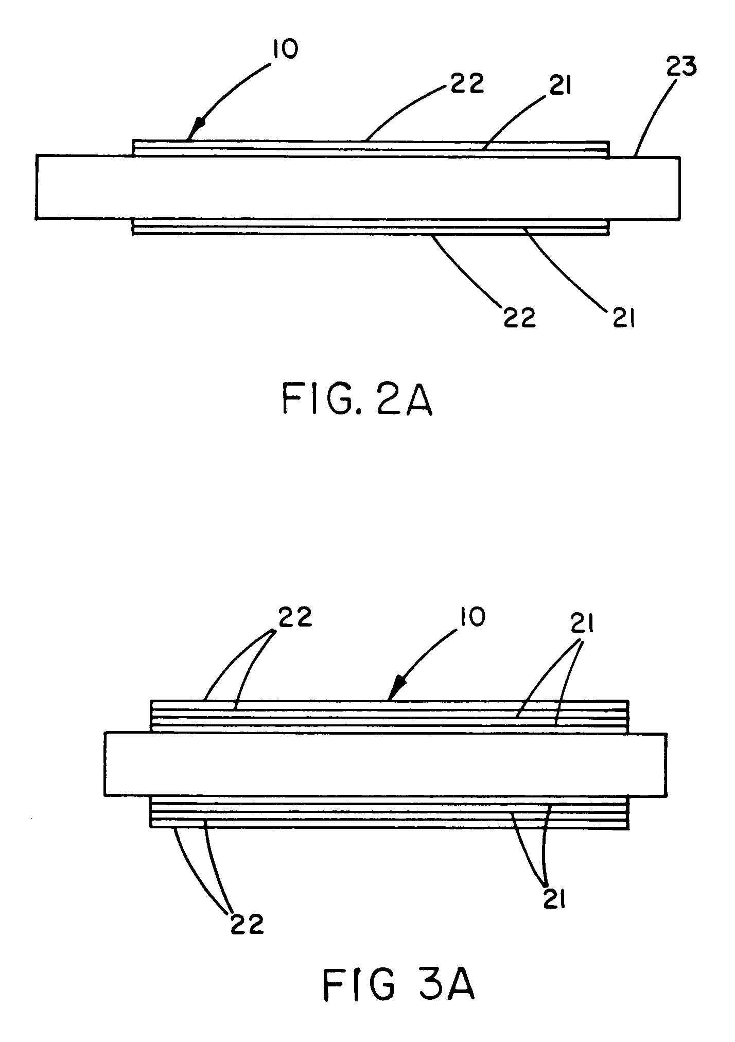
[0086]The first layer 21 of film was applied by wrapping a 6 mm diameter cylindrical stainless steel mandrel 23 with two 12.5 mm wide strips of the FEP-coated porous expanded PTFE film as shown by the transverse cross section of FIG. 8. The edges 81 of the two layers of longitudinally-oriented film overlapped by about 3 mm. The PTFE side of ...


PUM

PropertyMeasurementUnit
thicknessaaaaaaaaaa
thicknessaaaaaaaaaa
thicknessaaaaaaaaaa

Abstract

A thin-wall PTFE (polytetrafluoroethylene) tube in the form of a tube of porous expanded PTFE film wherein the porous PTFE film has a microstructure containing a multiplicity of fibrils. The thin-wall tube is used in a non-porous embodiment as the balloon portion of a balloon catheter. The thin-wall tube is not elastomeric; however, because of the thinness, strength and flexibility of the tube, it may be inserted into a body conduit in a collapsed state and then deployed from a catheter and inflated up to the maximum diameter of the thin-wall tube. The porous PTFE film is provided with a continuous layer of adhesive to provide the non-porous tube; the adhesive is preferably a thermoplastic and more preferably a thermoplastic fluoropolymer such as fluorinated ethylene propylene.

Description

CROSS-REFERENCE TO RELATED APPLICATIONS[0001]The present application is a continuation of application Ser. No. 08 / 247,960 filed May 24, 1994, now U.S. Pat. No. 6,027,779, which is a continuation-in-part of application Ser. No. 08 / 204,708 filed Mar. 2, 1994, now U.S. Pat. No. 6,025,044, which is a continuation-in-part of application Ser. No. 08 / 108,963 filed Aug. 18, 1993, now U.S. Pat. No. 6,159,565.FIELD OF THE INVENTION[0002]This invention relates to the field of thin-wall polytetrafluoroethylene tubes.BACKGROUND OF THE INVENTION[0003]Thin-wall polytetrafluoroethylene (hereinafter PTFE) tubes are useful for a variety of applications where the thinness of the tube wall and the lubricity of the PTFE are advantageous. The chemically inert character of the PTFE is also advantageous, particularly when the biocompatibility of the tubing is a concern.[0004]Conventional thin-wall PTFE tubes suffer from poor flexibility and have relatively poor mechanical strength characteristics, specific...

Claims


Application Information

Patent Timeline
Patent Type & Authority Patents(United States)
IPC IPC(8): B29D22/00B29D23/00B32B1/08A61B17/34A61F2/00A61F2/06A61L29/04A61L29/08A61L31/04A61L31/10B29C53/38B29C53/58B29C63/10B29C70/20B29C70/30B29D23/18F16L11/08
CPCA61L27/16A61L27/56A61L29/041A61L29/085A61L31/048A61L31/10B29C70/207B29C70/30B29D23/001B29D23/18B32B1/08B32B3/02B32B3/10B32B5/18B32B5/32B32B15/02B32B15/08B32B27/30F16L11/085A61F2/06C08L27/18A61B17/3431Y10T428/1362A61F2/07A61F2002/072A61F2002/075A61F2250/0067B29C53/38B29C53/58B29C63/10B29K2027/18B29K2105/04B29K2105/048B29K2105/0827B29K2105/101B29K2305/12B29L2009/00B29L2023/005B29L2023/007B29L2023/18B29L2031/14B29L2031/753B29L2031/7542Y10T428/1397Y10T428/139Y10T428/1393Y10T428/1355Y10T428/1352Y10S623/90B29L2022/022Y10T428/31544Y10T428/31504Y10T428/3154B29C70/302
Inventor GOFFENA, DONALD G. M.MYERS, DAVID J.
Owner GORE ENTERPRISE HLDG INC
Why Eureka
Try Eureka