Capacitive feedforward circuit, system, and method to reduce buffer propagation delay

Active Publication Date: 2007-10-09
MONTEREY RES LLC
View PDF4 Cites 12 Cited by
  • Summary
  • Abstract
  • Description
  • Claims
  • Application Information

AI Technical Summary

Benefits of technology

[0011]The buffer can comprise a single stage buffer, or two (or more) inverting stages. Moreover, the buffer can accommodate differential inputs and differential outputs, or a single-ended input and a single-ended output. The control circuit, pre-charge circuit, and coupling circuit can be used to capture the rising edge, capacitively couple the rising edge to the control circuit, and pre-charging the control circuit on the previous falling edge. Alternativel

Problems solved by technology

Unfortunately, however, in order to achieve a relatively short propagation delay, most buffer circuits consume considerable power.
However, the additional power consumption can be a significant penalty in the overall performance of the electronic system.
Eve

Method used


Image

  • Capacitive feedforward circuit, system, and method to reduce buffer propagation delay
  • Capacitive feedforward circuit, system, and method to reduce buffer propagation delay
  • Capacitive feedforward circuit, system, and method to reduce buffer propagation delay

Examples


Embodiment Construction

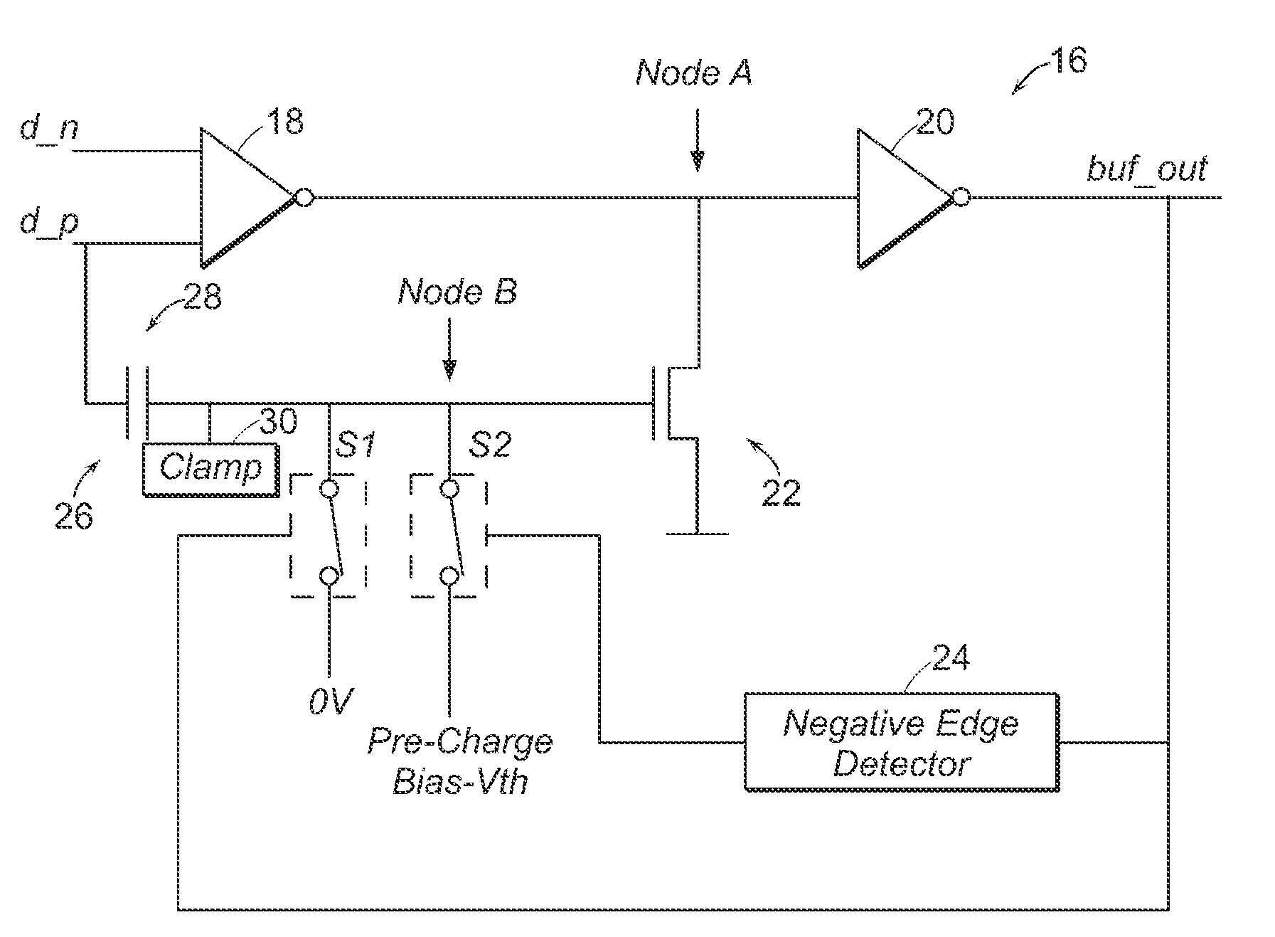
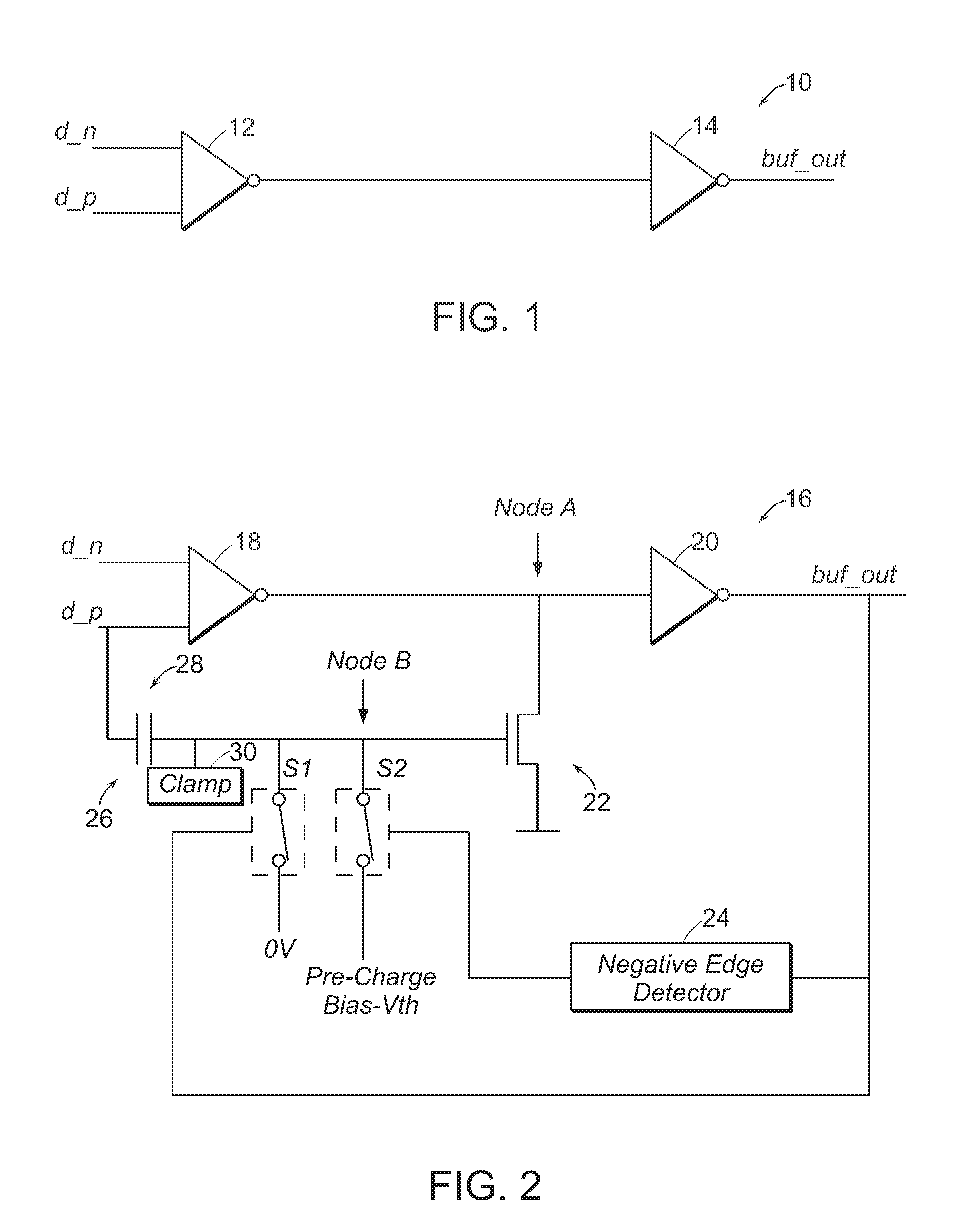
[0021]Turning now to the drawings, FIG. 1 illustrates a two-stage input buffer architecture 10 having a first stage 12 and a second stage 14. The first stage 12 can have differential inputs d_n and d_p, and a single inverted output. The second stage 14 can be either a single-ended input and single-ended output (as shown) or a differential input and differential output. It is recognized that the term “buffer” can include a single stage, two stages, or more than two stages, and the buffer can comprise differential (or complementary) inputs and outputs or a single-ended input and a single-ended output, or combinations thereof.

[0022]As used herein, the term “differential” refers to a pair of signals, wherein one signal is the logic state complementary of the other. In other words, if there is a differential input or differential output, the corresponding input and output comprise two conductors, and each conductor bears one of the complementary pair of signals. Thus, if the buffer has a...


PUM


Abstract

A buffer circuit, system, and method are provided. The buffer circuit includes a control circuit coupled to an output of the buffer, or possibly to an output of the first stage of a buffer. A pre-charge circuit is also provided coupled to bias an input of the control circuit to a voltage value approximately near a threshold voltage of the control circuit. The pre-charge bias amount is slightly less than the amount needed to place the control circuit in a high current conduction state. A coupling circuit is thereafter used and adapted to couple an input voltage applied to the buffer circuit to the input of the control circuit. This causes the control circuit to enter the high current conduction state. Depending on the input impedance of the coupling circuit, by pre-charging the coupling circuit input, less time is needed to cause the coupling circuit to enter and thereafter leave a high current conduction state. Therefore, by pre-charging the coupling circuit, output transitions from the buffer circuit can be accelerated and propagation delay reduced. The pre-charge circuit and the control circuit operate on one or more stages of a single or multi-stage buffer, operate on single-ended or differential/complementary input/output, and operate to speed up either the rising, falling, or both edges transitions at the output of the buffer.

Description

PRIORITY APPLICATION[0001]The present application claims priority to U.S. Provisional Application No. 60 / 661,313 entitled “Capacitive Feedforward Circuit, System and Method to Reduce Buffer Propagation Delay,” filed Mar. 10, 2005.BACKGROUND OF THE INVENTION[0002]1. Field of the Invention[0003]The present invention relates to an electronic system and, more particularly, to a buffer circuit that utilizes a pre-charge coupling circuit and a capacitively coupled feedforward signal to reduce the propagation delay within the buffer.[0004]2. Description of the Related Art[0005]The following descriptions and examples are not admitted to be prior art or conventional by virtue of their inclusion within this section.[0006]Electronic systems often use buffer circuits to receive external signals and convert those signals to appropriate voltage levels. Buffer circuits are often found in sequential electronic systems, such as those that use a regular and periodic clocking signal. Therefore, a buff...

Claims


Application Information

Patent Timeline
IPC IPC(8): H03K17/16H03K19/003
CPCH03K19/01721H03K17/04123
Inventor RICHMOND, GREGO'SULLIVAN, PAULA
Owner MONTEREY RES LLC
Why Eureka
Try Eureka