Method and apparatus for detecting the presence of flame in the exhaust path of a gas turbine engine

a gas turbine engine and exhaust path technology, applied in lighting and heating apparatus, optical radiation measurement, instruments, etc., can solve the problems of inability to respond to the radiant energy of hot surfaces, the thermal coupling cannot last for long periods, and the supply voltage is in excess of 325 volts dc, so as to achieve maximum fuel efficiency

Inactive Publication Date: 2007-10-16
MEGGITT NEW HAMPSHIRE
View PDF3 Cites 28 Cited by
  • Summary
  • Abstract
  • Description
  • Claims
  • Application Information

AI Technical Summary

Benefits of technology

[0011]Accordingly, it is an object of the instant invention to provide a method of determining the condition of the nozzle fouling to maximize fuel efficiency.

Problems solved by technology

The problem of the thermocouple prior art in addition to having too slow of a response time to adequately sense flame, thermocouples do not last for long periods in the highly oxidizing atmosphere of a gas turbine.
When properly constructed they are non-responsive to the radiant energy of hot surfaces in the combustion chamber.
Additionally they suffer from requiring supply voltages in excess of 325 volts DC.
The time durations of the flame events observed during our testing were so short (in the realm of a second or less), that thermocouple technology would not be responsive enough to accurately detect them.
Therefore the improvement in reducing unnecessary maintenance costs is minimal and not cost effective using a thermocouple because of the shortfalls consistent with that method of monitoring flame in the exhaust section of the turbine.

Method used


Image

  • Method and apparatus for detecting the presence of flame in the exhaust path of a gas turbine engine
  • Method and apparatus for detecting the presence of flame in the exhaust path of a gas turbine engine
  • Method and apparatus for detecting the presence of flame in the exhaust path of a gas turbine engine

Examples


Embodiment Construction

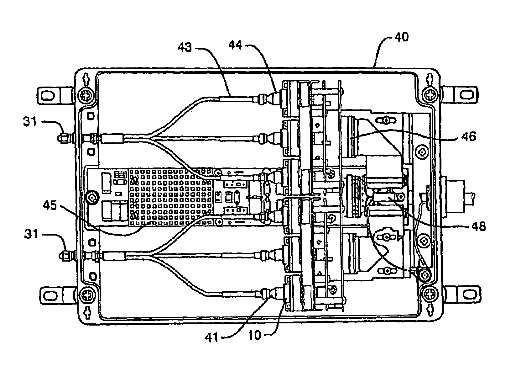
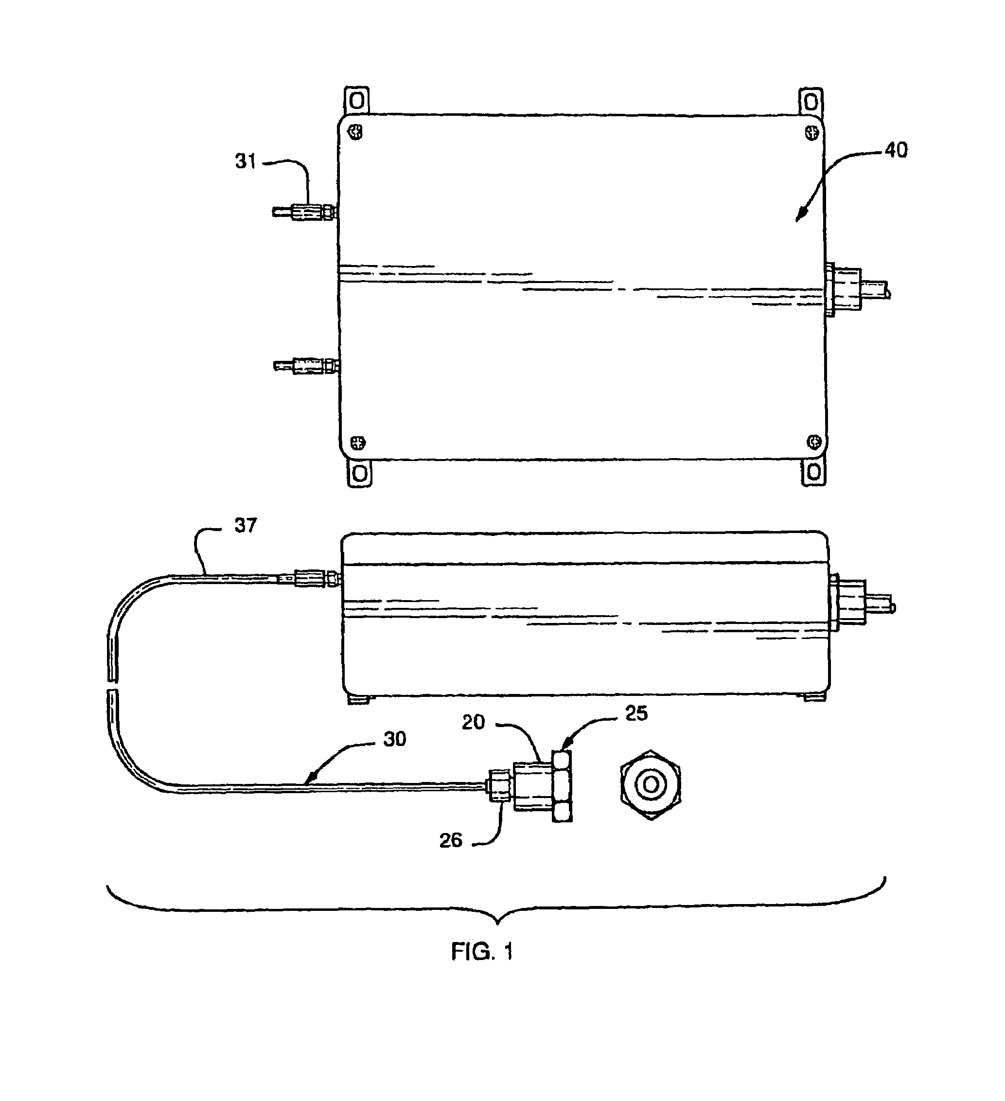
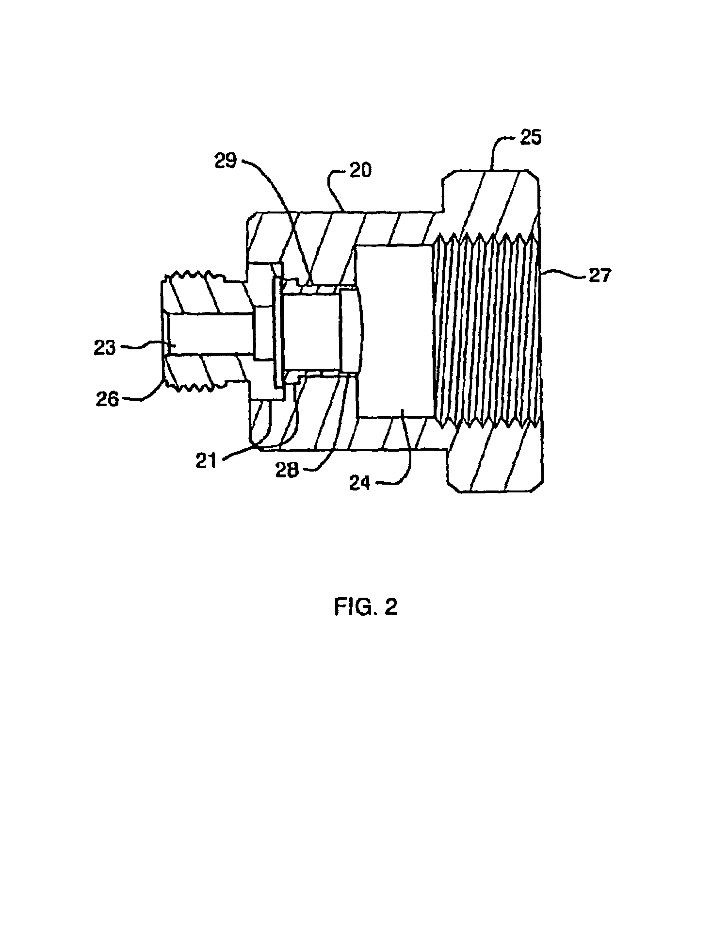
[0045]In reference to FIGS. 1–5, according to one potential embodiment of the present invention is at least one fiber optic flame sensor 10 for monitoring the presence and / or intensity of the flame in the exhaust section of a gas turbine engine generally consists of three component sections; a high temperature probe or optical viewing port 20, at least one fiber optic cable 30, and an Electro-Optics Module 40 (E.O.M.). As described in detail below, the high temperature probe / optical viewing port 20, mounts directly on the engine in a location, which will provide an adequate view into the exhaust portion of the turbine thus acting as a sight pipe. The fiber optic cable 30 transfers the radiant electromagnetic energy emitted by an uncontrolled combustion flame from the viewing port 20 to the E.O.M. 40. The E.O.M. 40 preferably contains solid-state electronics for converting a selected wavelength region of the radiant electromagnetic energy to an electrical signal that is monitored, in...


PUM


Abstract

A method and apparatus for monitoring the exhaust path of a gas turbine engine for the presence of unwanted flames downstream from the main combustion chamber(s). The system is comprised of an Electro-Optics Module containing sensors and associated processing electronics as well as collection and transmitting optics, which relay the radiant energy generated by a flame event to the sensors. The information generated by the sensors is directly related to the time based intensity of the flame event, which can suggest problems associated with the condition of combustion related engine components. This information can then be used by the engine owner / operator to assess the condition of the engine and determine the more efficient required maintenance schedule.

Description

CROSS-REFERENCE TO RELATED APPLICATIONS[0001]This application claims the benefit of U.S. Provisional Application No. 60 / 388,604, filed Jun. 3, 2002, the contents of which are incorporated in their entirety. The application claims benefit to PCT / US03 / 17040 filed Jun. 3, 2003, which is incorporated herein by reference in its entirety.FIELD OF THE INVENTION[0002]This invention relates to flame detection, and especially to a solid state, fiber optic linked flame sensor that is particularly useful in connection with sensing the flame in a gas turbine exhaust path as a means of determining the condition of the fuel nozzle(s).BACKGROUND OF THE INVENTION[0003]The life cycle cost reduction for capital equipment such as gas turbines is of great importance to end users such as the Navy, the shipping industries and power generation stations to name a few. Regular maintenance of gas turbine equipment by the operators is necessary to maximize performance and fuel efficiency however the associated...

Claims


Application Information

Patent Timeline
Patent Type & Authority Patents(United States)
IPC IPC(8): F02C7/00F01D17/08F01D21/14F02K3/10F23M11/04F23N5/24
CPCF01D17/08F01D21/14F02K3/10F23M11/047F23N5/082F23N5/242G01J5/0014G01J5/0018G01J5/0088G01J5/08G01J5/0821G01J5/0846G01J5/0862G01J5/0893F01D21/003Y02T50/671F05D2270/083F23N2029/00G01J5/0205G01J5/025Y02T50/677F23N2229/00Y02T50/60G01J5/0802F02C7/00
Inventor PLIMPTON, JONATHONJUBINVILLE, LEODUCKLESS, EDWARD
Owner MEGGITT NEW HAMPSHIRE
Why Eureka
Try Eureka