
Charged particle beam detection system

a detection system and charge technology, applied in the direction of particle separator tube details, mass spectometers, nuclear elements, etc., can solve the problems of low accuracy, low cost, and low design consideration of ease, cost and speed of manufacture, and achieve low cost, simplify the use of array technology, and high spatial resolution

Inactive Publication Date: 2007-10-16
UNIV OF WASHINGTON
View PDF24 Cites 14 Cited by
  • Summary
  • Abstract
  • Description
  • Claims
  • Application Information

AI Technical Summary

Benefits of technology

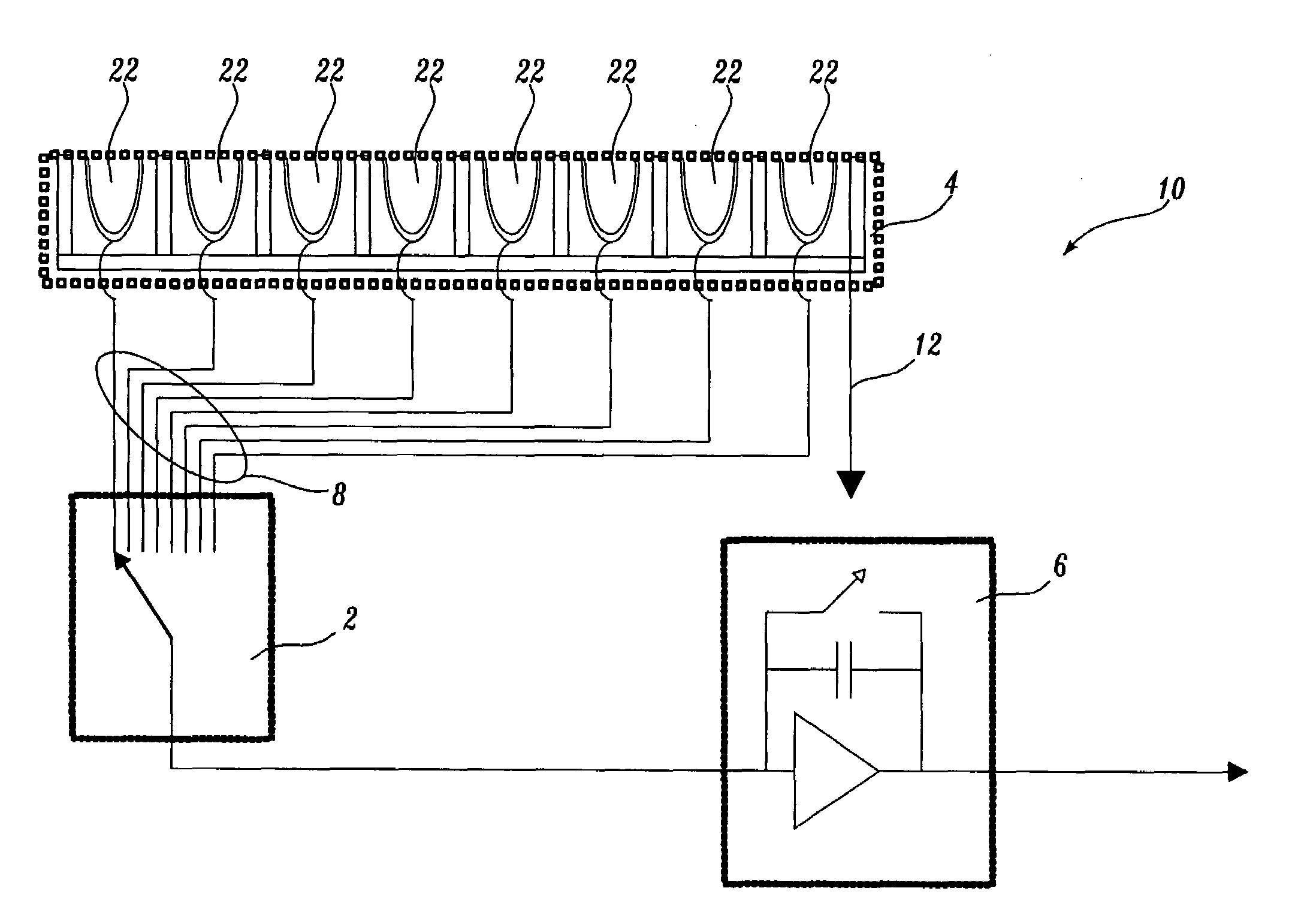
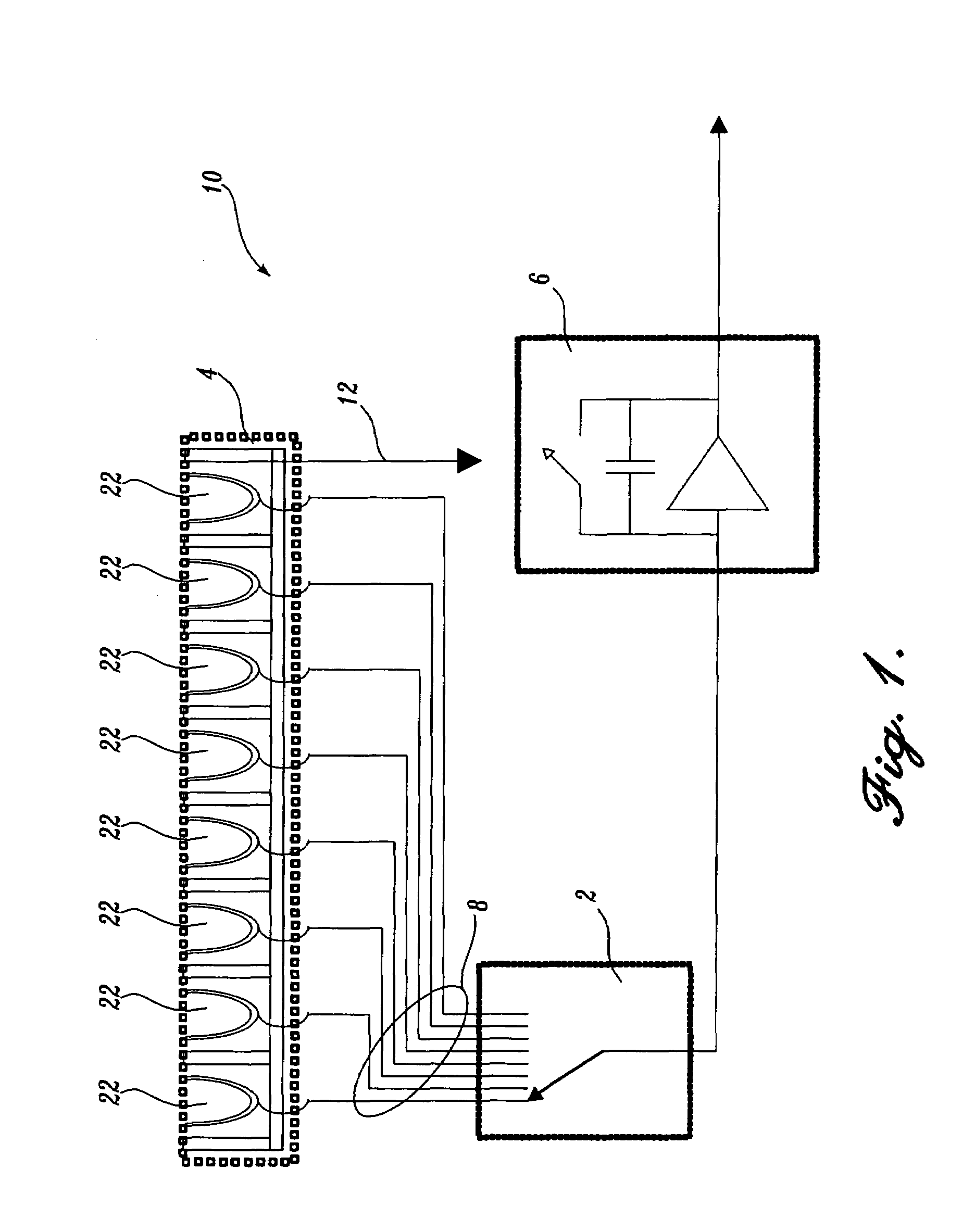
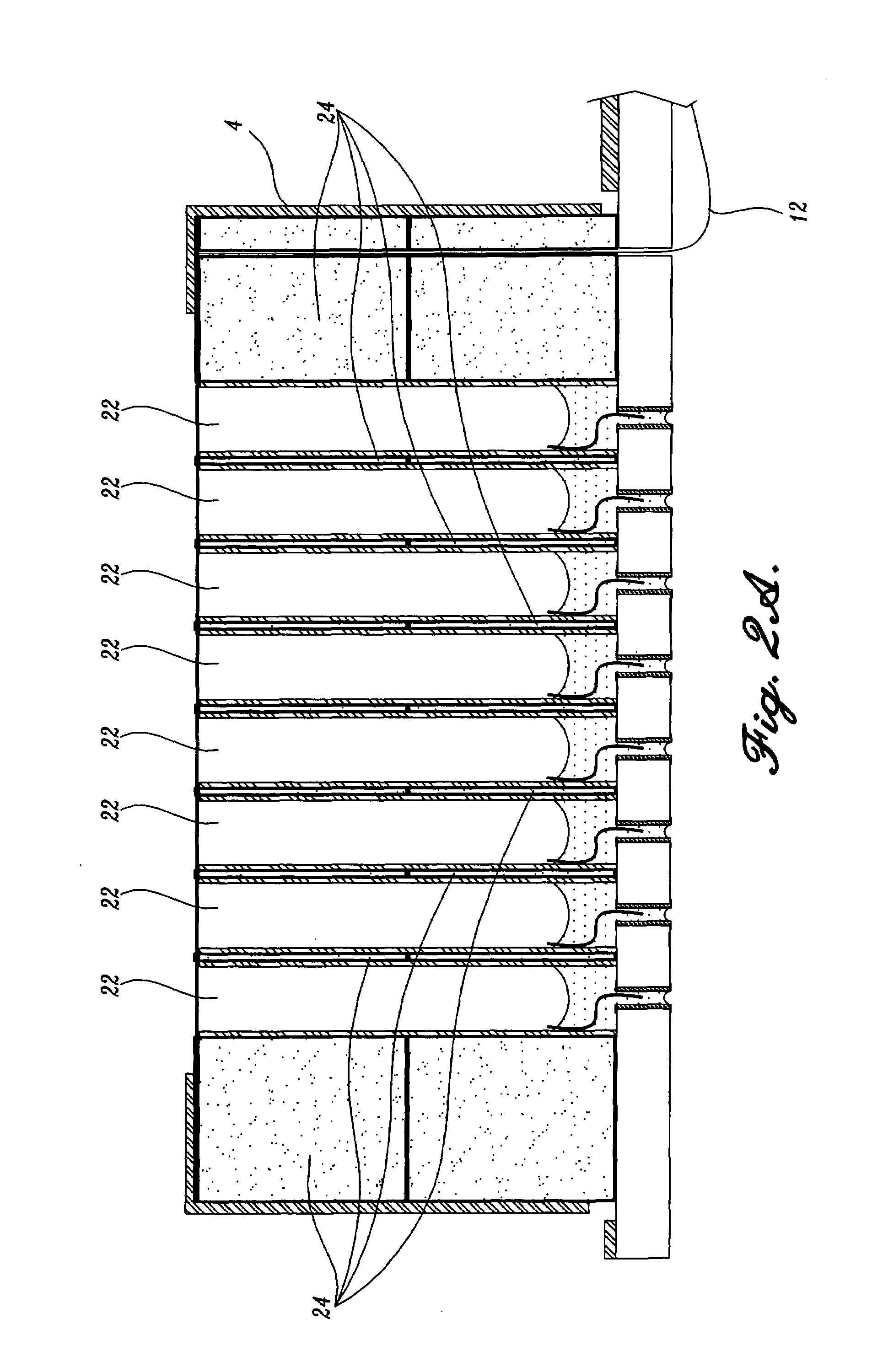
[0012]Embedding the Faraday cups in a (grounded) conducting housing, provides a small cup-to-cup capacity, which, by combining the FCDA with an electronic multiplexing unit based on a Gray-code, has then the unique capability to monitor the entire array simultaneously with a duty cycle >98%, and having a crosstalk level better than 750:1, despite the fact that the Faraday cups are packed densely. Therefore, a large fill factor (defined as the ratio of the “active opening area” to the “overall size of the detector array”) can be achieved.
[0036]The present invention employs the advantages of a Faraday cup to a fine spatial distribution measurement of an ion or electron beam. The present invention provides a FCDA and its electronic interface that is both a platform for a 250 μm resolution device and a low-cost method for position-sensitive particle detection. The device employs the advantages of a Faraday cup with a spatial resolution ranging from 250 mm to 0.1 inch and can be interfaced with data acquisition electronics. Such a configuration simplifies the use of array technology because only six feedthroughs are needed to read out the array, and most of the electronics are integrated with the system. Furthermore, the invention provides a low-cost method to produce long arrays of Faraday cup units, which are useful in devices such as mass spectrometers of the Herzog-Mattuch design where the ions are mass separated spatially in a focal plane. T. W. Burgoyne, et al. “Design and performance of a plasma-source mass spectrograph”, J. Am. Soc. Mass Spectrometry, Vol. 8, 307–318, 1997. Thus, in another embodiment, the invention provides a microfabricated FCDA that has very high spatial resolution. The microfabricated FCDA can be manufactured at low cost and in high volume as seen in MEMS technology.

Problems solved by technology

Therefore, Faraday cups are not as sensitive as electron multipliers or microchannel plate detectors, which have single charged particle counting capabilities.
Typically, designs do not consider ease, cost, and speed of manufacture, since they are for specialized applications, such as measuring beam profiles in experimental apparatuses or very high-cost electron microscopes.
However, they all lack linearity, ruggedness, and their amplification characteristics degrade over time.
Furthermore, these devices cannot measure absolute ion currents if they are not particle counting, and are of only limited use in poor vacuum conditions, as found in the next generation of miniaturized mass spectrometers, such as portable or spacecraft-based instruments (M. P. Shiha, et al., “Development of a Miniature Gas Chromatograph—Mass Spectrometer,”Anal.
Finally, these solutions are cost intensive.
Faraday cup arrays have been developed for ion beam profiling purposes, but have been too large to be of use if high resolution is desired.
Because applications have been specialized, present devices have not combined the previous requirements with the additional ones of ease, cost, and speed of manufacture.

Method used


Image

  • Charged particle beam detection system
  • Charged particle beam detection system
  • Charged particle beam detection system

Examples


Embodiment Construction

[0051]The present invention provides a Faraday cup detector array (FCDA) for charged particle beam detection. The detector being an array of Faraday cups means that the detector is position sensitive. By combining the FCDA with a properly synchronized electronic multiplexing unit (MUX), the resulting instrument has the unique capability to simultaneously monitor the entire array of Faraday cups with a duty cycle approaching 100%. The high duty cycle is achieved by collecting the ions with a large number of small, electronically decoupled Faraday cups. Because Faraday cups collect incident ions independent of their charge state, each cup is both a charged particle collector and a charge integrator. The ability of a Faraday cup to integrate the charge, in combination with the electronic multiplexing unit, which quickly reads out (and empties) the cups compared to the charge integration time of the array, provides the almost perfect duty cycle for such position-sensitive charged partic...


PUM

PropertyMeasurementUnit
Dimensionsaaaaaaaaaa

Abstract

A charged particle beam detection system that includes a Faraday cup detector array (FCDA) for position-sensitive charged particle beam detection is described. The FCDA is combined with an electronic multiplexing unit (MUX) that allows collecting and integrating the charge deposited in the array, and simultaneously reading out the same. The duty cycle for collecting the ions is greater than 98%. This multiplexing is achieved by collecting the charge with a large number of small and electronically decoupled Faraday cups. Because Faraday cups collect the charge independent of their charge state, each cup is both a collector and an integrator. The ability of the Faraday cup to integrate the charge, in combination with the electronic multiplexing unit, which reads out and empties the cups quickly compared to the charge integration time, provides the almost perfect duty cycle for this position-sensitive charged particle detector. The device measures further absolute ion currents, has a wide dynamic range from 1.7 pA to 1.2 μA with a crosstalk of less than 750:1. The integration of the electronic multiplexing unit with the FCDA further allows reducing the number of feedthroughs that are needed to operate the detector.

Description

CROSS-REFERENCES TO RELATED APPLICATIONS[0001]This application is a divisional of U.S. patent application Ser. No. 09 / 744,360, filed Jan. 22, 2001, now U.S. Pat. No. 6,847,036, which is the national stage filing of International Application No. PCT / US99 / 23307, designating the United States, filed Oct. 6, 1999, which claims the benefit of U.S. Provisional Application No. 60 / 116,710, filed Jan. 22, 1999.FIELD OF THE INVENTION[0002]The present invention relates in general to a charged particle beam detection system and, in particular, to a Faraday cup detector array useful in mass spectrometry.BACKGROUND OF THE INVENTION[0003]The inner walls of any metallic body are free of charge and electrostatic fields. Therefore, if a charged particle external to a metallic cup hits the inside of the cup and is neutralized there, the accumulated charge will flow to the outer surface of the cup. This implies that it is possible to achieve a very high charge state of the cup by depositing charge on t...

Claims


Application Information

Patent Timeline
Patent Type & Authority Patents(United States)
IPC IPC(8): H01J40/00G01N27/00G01T1/29G21F1/00H01J37/04H01J49/02H01J49/10H01J49/26
CPCH01J49/10H01J49/025H01J2237/24507H01J2237/24542
Inventor DARLING, ROBERT BRUCESCHEIDEMANN, ADI A.SCHUMACHER, IV, FRANK J.JONES, PATRICK L.
Owner UNIV OF WASHINGTON
Learn More