Thermal air flow rate measuring apparatus and its flowmeter and internal combustion engine and thermal air flow rate measuring method using it

Inactive Publication Date: 2007-10-23
HITACHI LTD +1
View PDF30 Cites 28 Cited by
  • Summary
  • Abstract
  • Description
  • Claims
  • Application Information

AI Technical Summary

Benefits of technology

[0019]In a hot-wire type air flow meter for measuring an intake air flow rate of an internal combustion engine used in a vehicle or the like, the present invention provides devices different in the flow rate measuring ranges corresponding to various uses, and improves the measurement accuracy by adjusting the total sensi

Problems solved by technology

Particularly in vehicles, in a case of pulsating flow having a large pulsating amplitude of an intake air flow rate and partial reversed flow, which may take place under a low rotation speed and a heavy load condition in an engine having

Method used


Image

  • Thermal air flow rate measuring apparatus and its flowmeter and internal combustion engine and thermal air flow rate measuring method using it
  • Thermal air flow rate measuring apparatus and its flowmeter and internal combustion engine and thermal air flow rate measuring method using it
  • Thermal air flow rate measuring apparatus and its flowmeter and internal combustion engine and thermal air flow rate measuring method using it

Examples


embodiment 1

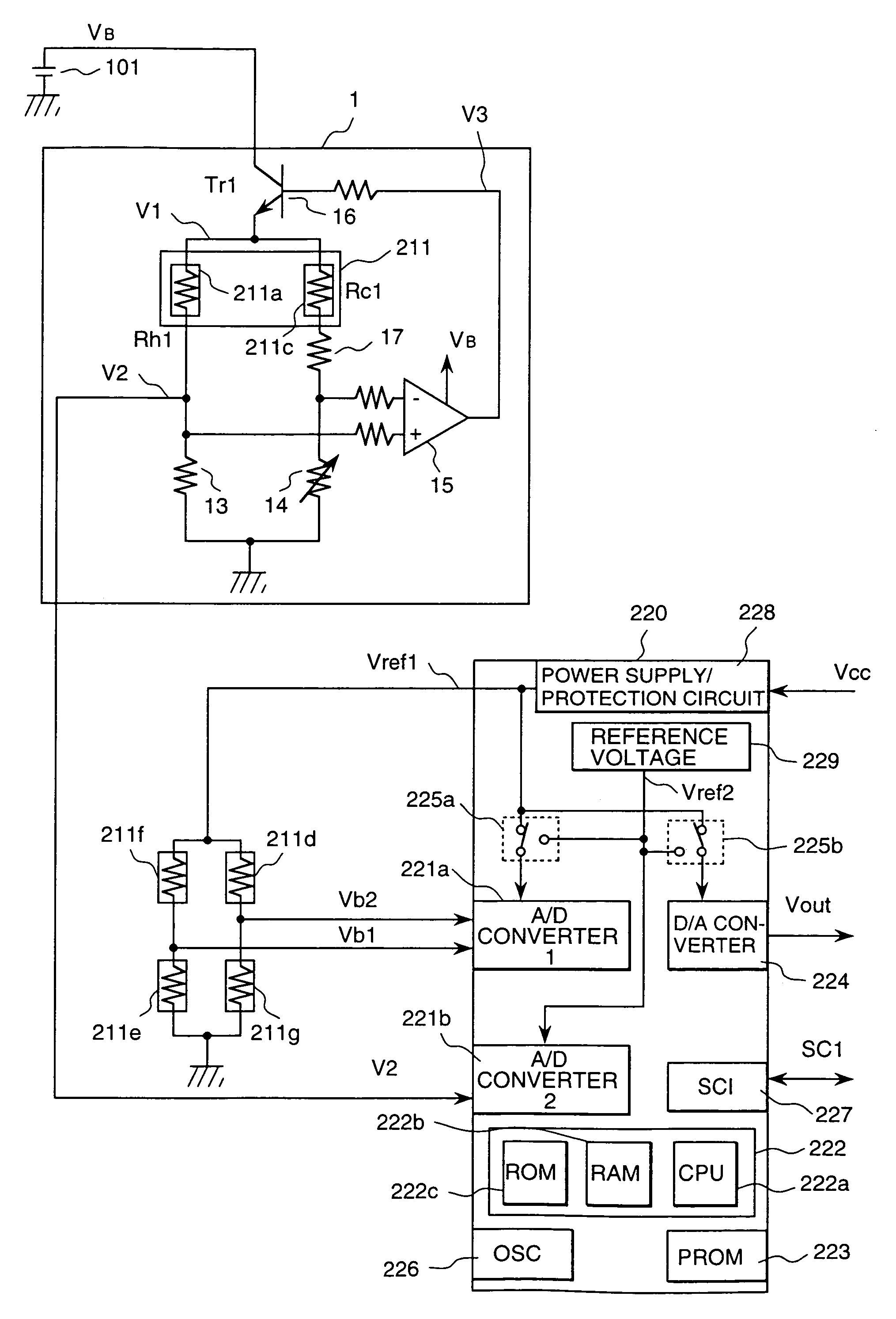
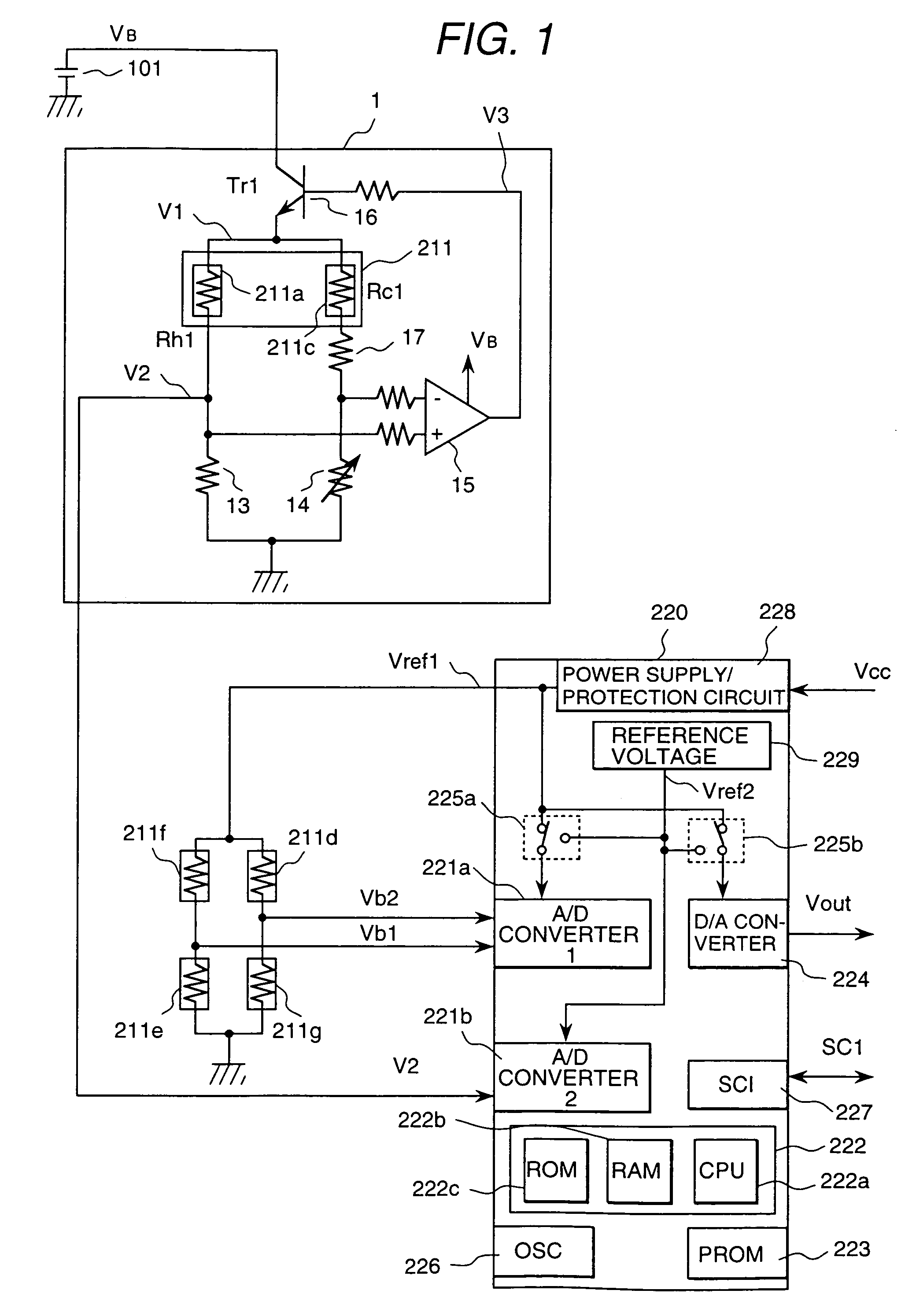
[0043]FIG. 1 is a diagram showing a drive circuit of a thermal air flow rate measuring apparatus according to the present invention. A hot-wire drive circuit 1 is connected to a power source 101 to output a signal corresponding to an air flow rate. The hot-wire drive circuit 1 comprises a Wheatstone bridge composed of a heating resistor 211a, a temperature compensation resistor 211c and resistors 13, 14 and 17, and is constructed in such a manner that current flowing through the heating resistor 211a can be controlled by a differential amplifier 15 and a transistor 16 to make an electric potential difference between the midpoints of the bridge zero. When the heated temperature of the heating resistor 211a is low, an output of the differential amplifier 15 becomes large so as to further heat up the heating resistor 211a. By this construction, the resistance value of the heating resistor 211a is controlled at a constant value independently of the flow rate, that is, the current flowin...

embodiment 2

[0082]FIG. 10 is a diagram showing a driving circuit of the thermal air flow meter in accordance with the present invention. This embodiment is an example in which the reference voltage circuit in the digital correction circuit 220 is arranged in the outside, compared to the embodiment of FIG. 1. The hot-wire drive circuit 1 is connected to the power supply 101, and outputs a signal corresponding to an air flow rate. The power source circuit 5 is also connected to the power supply 101, and a voltage Vref3 is produced by the reference voltage circuit 51. The voltage Vref3 is supplied as the electric power to the digital correction circuit 220 and to the bridge circuit composed of the temperature detecting resistors 221d, 221e, 221f and 221g.

[0083]In the present embodiment, the electric potentials Vb1 and Vb2 of the bridge midpoints of the temperature detecting resistors 221d, 221e, 221f and 221g are inputted to the analog-digital converter 221c of the digital correction circuit 220 ...

embodiment 3

[0094]FIG. 13 is a diagram of a driving circuit of the thermal air flow meter in accordance with the present invention. Even if the external voltage Vcc is directly inputted to the analog-digital converter 221c and the operation of the dependency of the external voltage is executed in the digital correction circuit 220, as shown in FIG. 13, it is possible to easily obtain the same effect as the effect of the aforementioned embodiments. Further, by imputing the voltage at the both ends of the temperature compensation resistor 211c to the digital correction circuit, the intake air temperature can be calculated, and the voltage can be used for the correction of the intake air temperature and the output of the intake air temperature. In the present embodiment, an analog output of the intake air temperature is realized by providing the digital-analog converter 224b. According to the present embodiment, by using the analog-digital converter having a great number of channels, it is possibl...


PUM


Abstract

A thermal air flow rate measuring apparatus of great precision wherein sensitivity is enhanced by sensors having different output characteristics and an operating device employing a digitized signal. The sensitivity and temperature can be corrected easily depending on the flow direction of fluid. The measuring apparatus includes at least one heating resistor disposed in a gas fluid, temperature detecting resistors formed at an upstream part and a downstream part of the heating resistor in the flow direction of the fluid, a device for outputting at least two signals relating to the flow rate of the fluid, a quantizing device for quantizing the output values, and an operating device for operating the flow rate based on the quantized signals.

Description

TECHNICAL FIELD[0001]The present invention relates to a novel thermal air flow rate measuring apparatus and a novel thermal air flow rate measuring method, and to an internal combustion engine using the thermal air flow rate measuring apparatus and a thermal air flow rate measuring method suitable for detecting an intake air flow rate of the internal combustion engine.BACKGROUND ART[0002]As an air flow rate apparatus for measuring an intake air flow rate arranged in an electronically controlled fuel injection unit of an internal combustion engine in a vehicle or the like, air flow rate measuring apparatuses of thermal type have been widely used because of capability of directly detecting a mass air flow rate. Therein, its heating resistor is constructed by winding a platinum wire around a bobbin and then coating the wire with glass, or by forming a thin film resistor on a ceramic substrate or a silicon substrate.[0003]As the methods of detecting a flow rate, there are a type in whic...

Claims


Application Information

Patent Timeline
IPC IPC(8): G01F1/68G01F1/684G01F1/696G01F1/698G01F1/72G01F15/04
CPCG01F1/6845G01F1/6965G01F1/72G01F1/6983G01F1/698
Inventor KANKE, ATSUSHIYAMADA, MASAMICHIIGARASHI, SHINYAYONEDA, HIROSHIOHTA, KENJI
Owner HITACHI LTD
Why Eureka
Try Eureka