Confocal imaging equipment in particular for endoscope

a technology of endoscope and imaging equipment, which is applied in the field ofconfocal imaging equipment, can solve the problems of low ratio of useful backscattered signal to parasitic signal, degradation of illumination beam with respect to both energy and space, etc., and achieves the effects of improving image quality, improving illumination beam quality, and simple implementation

Active Publication Date: 2007-10-23
MAUNA KEA TECHNOLOGIES
View PDF12 Cites 42 Cited by
  • Summary
  • Abstract
  • Description
  • Claims
  • Application Information

AI Technical Summary

Benefits of technology

[0009]The present invention has the aim of proposing an equipment with an improved quality of the illumination beam at the image guide input and as a result an image quality also improved. It also has the aim of proposing a solution, which is low-cost, simple to implement, and which can be miniaturized and produced industrially.SUMMARY OF THE INVENTION
[0014]Thanks to these optical means, it is possible to guarantee a quality of the illumination beam and a homogeneous and optimal level of coupling fibre by fibre.
[0015]Each optical system can comprise either a set of standard lenses making it possible to carry out the scanning and the injection into the image guide coupled with custom-made additional lenses having the function of correcting the residual aberrations of standard lenses, or a set of custom-made lenses of very good quality.
[0016]According to a particular example, an afocal optical system comprises four lenses, a corrective doublet of which being placed symmetrically relative to the image plane makes it possible to correct the curvature of field and minimize the wave front error.

Problems solved by technology

In the case of the analysis of a biological tissue, the difficulties that are encountered are linked to the low ratio of useful backscattered signal to parasitic signal, which, in order for the image produced to be acceptable, requires a quality of illumination beam which is the best possible and preserved throughout the optical path, in particular regarding the quality of the wave front and the spatial distribution of the focal spot intensity which must be as close as possible to the diameter of a fibre core.
On the side of the proximal end of the image guide, the degradation of the illumination beam with respect to both energy and space is in particular due to the parasitic reflections occurring at the image guide input and to optical transmission faults at the scanning and injection systems (field deformation, wave front error).

Method used


Image

  • Confocal imaging equipment in particular for endoscope
  • Confocal imaging equipment in particular for endoscope

Examples


Embodiment Construction

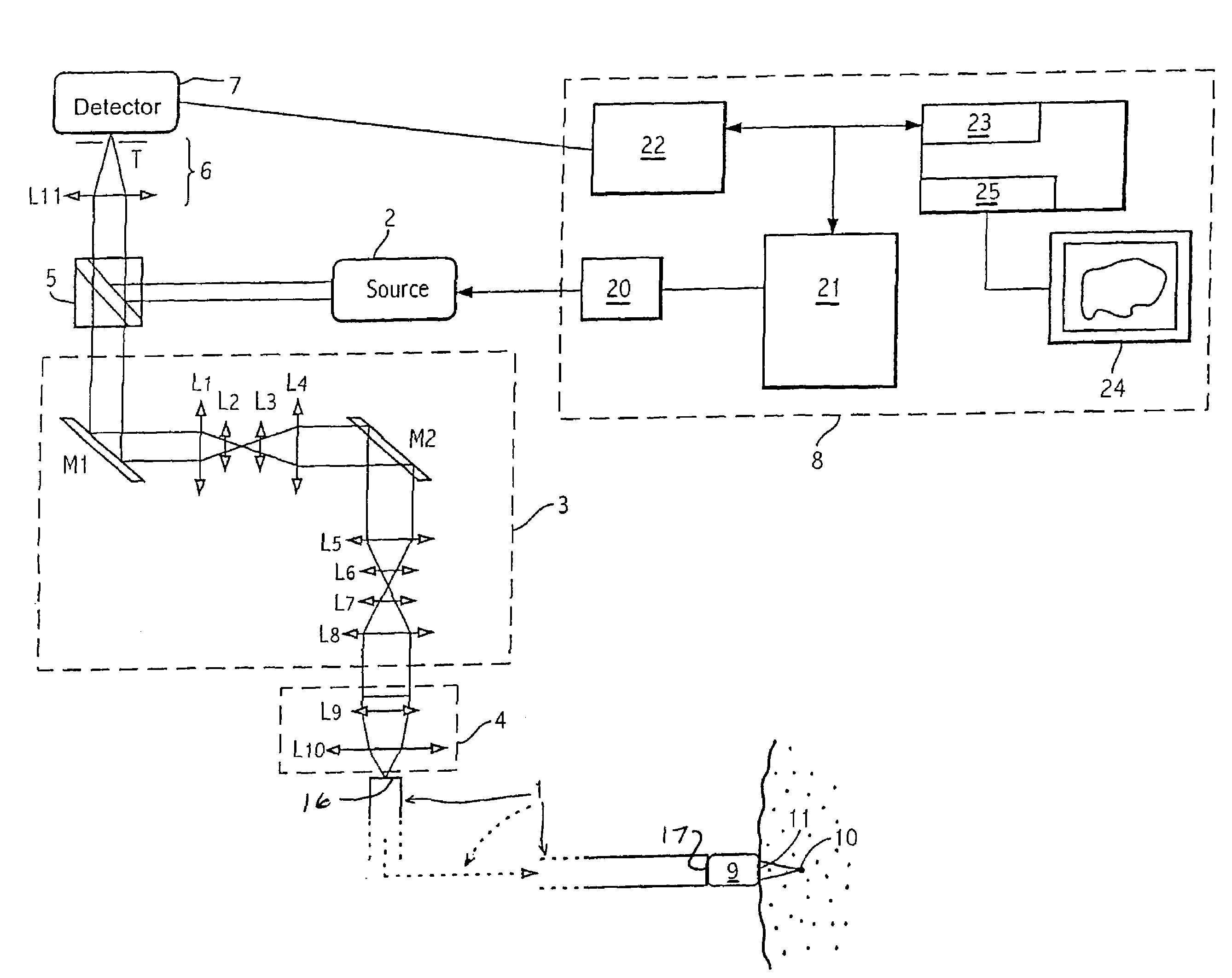
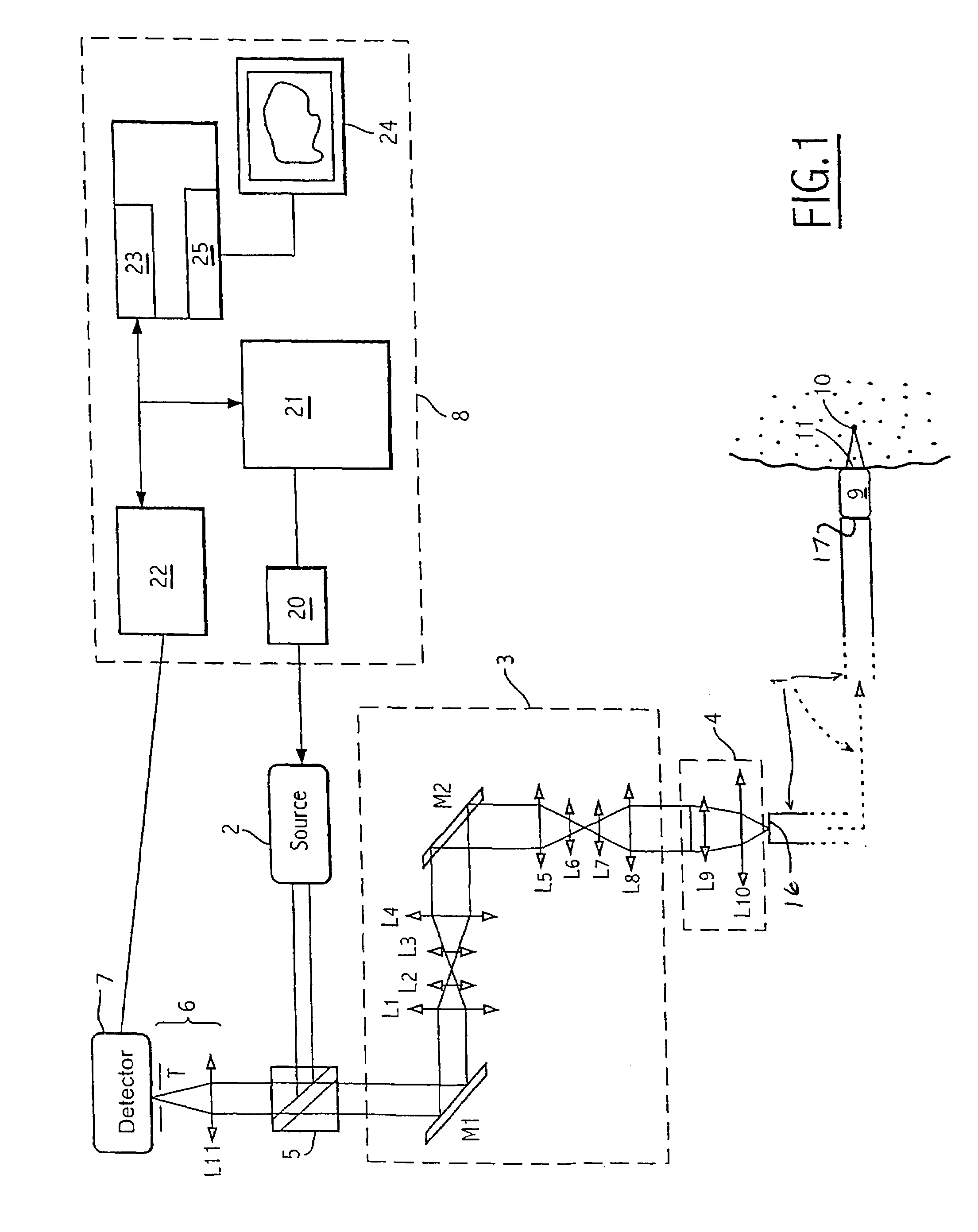
[0020]In FIG. 1, an equipment is proposed for producing an image of a site situated at a given depth in a plan P of section XY perpendicular to the optical axis, said equipment comprising an image guide 1 constituted by several tens of thousands of flexible optical fibres with:

[0021]on the side of the proximal end of the image guide 1: a source 2 producing an illumination beam, means for angular scanning 3 of said beam, means for injecting 4 the beam deflected alternately into one of the fibres of the image guide 1, means for separating 5 the illumination beam and the backscattered signal, means for spatial filtering 6, means of detecting 7 said signal, electronic means 8 for controlling, analyzing and digital processing of the detected signal and for displaying; and

on the side of the distal end of the image guide 1: an optical head 9 adapted for focusing the illumination beam leaving the illuminated fibre of the image guide into a focussed point 10 in the plane P under the contact ...


PUM


Abstract

Equipment includes an image guide (1) consisting of flexible optical fibers with: on the proximal end side: a source (2), angular scanning elements (3), injection elements (4) in one of the fibers, elements for splitting (5) the illuminating beam and the backscattered signal, elements for spatial filtering (6), elements for detecting (7) the signal, electronic elements (8) for controlling, analyzing and digital processing of the detected signal and display; and on the distal end side: an optical head (9) for focusing the illuminating beam exiting from the illuminated fiber. The scanning elements include a resonant line mirror (M1) and a galvanometric field mirror (M2) with a variable frequency and two afocal optical systems adapted to conjugate the two mirrors (M1, M2) firstly in the field mirror (M2) and the injection elements (4) in the image guide in a second step.

Description

FIELD OF THE INVENTION[0001]The present invention relates to a confocal imaging equipment in particular for an endoscope and of the type using a flexible optical fibre bundle. The confocal character resides in the use of the same path for illumination and detection, and in the spatial filtering of the signal collected from the subsurface analysis plane.[0002]The fields of application of the invention are in-vivo biological tissue analyses, on humans or animals, external, for example in the field of dermatology, or internal and accessible using the instrument channel of an endoscope into which the flexible optical fibre bundle can be introduced, and also the ex-vivo analysis of tissue samples from biopsies, and the in-vitro analysis of culture in cell biology. Moreover also, the device can serve for the analysis of the interior of a manufactured device.BACKGROUND OF THE INVENTION[0003]At present the medical fields of gastroenterology, respirology, gynaecology, urology, otorhinolaryng...

Claims


Application Information

Patent Timeline
Patent Type & Authority Patents(United States)
IPC IPC(8): A61B1/06G02B26/08A61B1/00G02B23/26A61B1/04A61B1/07G02B21/00G02B23/24
CPCA61B1/00188A61B1/00165G02B23/2469A61B1/07A61B1/042A61B2562/0242
Inventor VIELLEROBE, BERTRANDGENET, MAGALIEBERIER, FREDERICLACOMBE, FRANCOISPERCHANT, AYMERICLE GOUALHER, GEORGESMARTI, SANDRABOURRIAUX, STEPHANE
Owner MAUNA KEA TECHNOLOGIES
Why Eureka
Try Eureka