Eureka AIR delivers breakthrough ideas for toughest innovation challenges, trusted by R&D personnel around the world.

Systems for ultrasonic imaging of a jaw, methods of use thereof and coupling cushions suited for use in the mouth

a technology of ultrasonic imaging and jaw, applied in the field of jaw ultrasonic imaging system, methods of use thereof, coupling cushions suited for mouth use, can solve the problems of inability to accurately inability to detect the presence of a single sound wave, etc., to facilitate the translational motion of the wand, facilitate imaging

Inactive Publication Date: 2007-10-23
IMADENT
View PDF18 Cites 56 Cited by
  • Summary
  • Abstract
  • Description
  • Claims
  • Application Information

AI Technical Summary

Benefits of technology

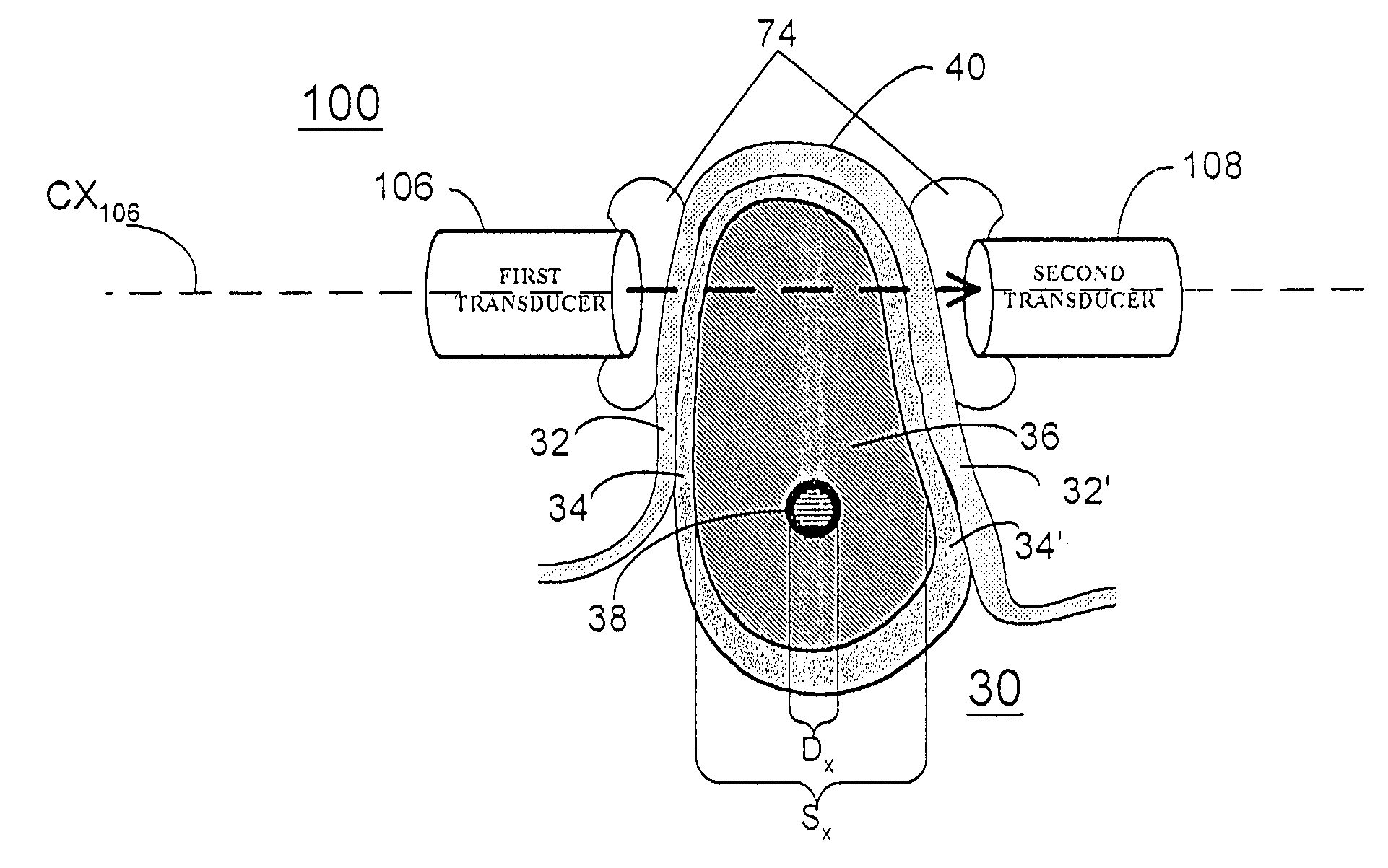
[0025]According to still further features in the described preferred embodiments the probe is a mandibular probe designed and constructed to facilitate imaging of at least a portion of a lower jaw. The mandibular probe includes: (i) a first array of ultrasonic transducers mounted upon a first wand, the first array of ultrasonic transducers positionable distal to the lower jaw and outside of a mouth; (ii) a second array of ultrasonic transducers, the second array of transducers mounted upon a second wand, the second array of ultrasonic transducers positionable proximal to the lower jaw and inside of the mouth; and (iii) at least one connective member. The connective member designed and constructed to connect the first and second wands one to another and to allow relative positioning thereof. The connective member includes an assembly designed and constructed to attach the first and second wands and facilitate translational motion of the wands with respect to one another.
[0031]According to still further features in the described preferred embodiments providing a probe includes providing a mandibular probe designed and constructed to facilitate imaging of at least a portion of a lower jaw and includes: (i) providing a first array of ultrasonic transducers mounted upon a first wand, the first array of ultrasonic transducers positionable distal to the lower jaw and outside of a mouth; (ii) providing a second array of ultrasonic transducers, the second array of transducers mounted upon a second wand, the second array of ultrasonic transducers positionable proximal to the lower jaw and inside of the mouth; (iii) providing at least one connective member, the connective member designed and constructed to connect the first and second arrays one to another and to allow relative positioning thereof. The connective member includes an assembly designed and constructed to attach the first and second wands and facilitate translational motion of the wands with respect to one another.

Problems solved by technology

However, such imaging techniques suffer from several significant disadvantages.
Such damage can ultimately lead to severe pain, hemorrhage and even local paralysis, among other undesired consequences.
However, if the implantologist is not aware of the internal structure and shape of the jawbone (e.g. the location of signal and / or nasal cavities 60), the implantologist may perforate and damage cortical floor 58.
Such perforation may lead to a serious signal infection and hemorrhage, as well as other undesired consequences.
First, it is well established that X-ray radiation is hazardous to the health of the patient.
This limitation makes the panoramic image unreliable for guiding the implantologist to drill within the bone boundaries and within a safe distance from the mandibular canal, or the signal\nasal cavities.
The panoramic image is inherently distorted and inaccurate because it projects the three-dimensional jaw into a two-dimensional image.
This image is therefore unreliable also for assessing the depth of the bone tissue available for drilling and preparing a fixture.
Third, the image is not taken chair-side and consequently, panoramic X-ray does not allow for real-time monitoring of implant procedures.
All of the above disadvantages make the panoramic X-ray image a hazardous, imprecise, and unreliable imaging solution.
However, CT involves a substantially higher dosage of X-ray radiation than conventional radiography, and therefore poses a significantly greater risk to the health of the patient.
Furthermore, CT equipment is very expensive and is only rarely found inside the clinic of the implantologist.
CT can definitely not provide a chair-side imaging solution.
However, ABMS still comes short of answering the needs of the dental implantologist for the following reasons.
First, measurement of time-of-flight (TOF) from a location on the surface of the alveolar bone to a non-bone canal inside the jaw is, in reality, impracticable or at least very imprecise due to the high level of attenuation and scattering inside the jawbone.
Thus, even in the case that ABMS manages to take a precise TOF measurement, it will still not be able to calculate the precise distance from the probe to the canal due to an error in the velocity of ultrasound.
Third, ABMS does not disclose any mechanism or procedure for ensuring that the echo which is supposedly from the canal and on which the distance measurement is based, is really from the canal and not from another reflector inside the jawbone.
Fourth, ABMS is limited to measuring the distance from the canal to the alveolar bone, and does not teach how to measure the distance between the canal and the buccal and lingual walls of the jawbone, which is of significant importance to the implantologist, e.g. in order to determine an optimal angle of drilling.
Lastly, being a measurement system rather than an imaging system, the most ABMS can provide is a numerical distance measurement from the location where the probe is located to a canal within the bone, but no implantologist will suffice with a mere numerical value as a basis for planning or performing a drill into a jaw.
The '279 patent suffers from limitations similar to those of ABMS, namely, impracticable or imprecise measurement and insufficient information to the implantologist.
As a result, both these patents provide only a two-dimensional attenuation map of the examined bone which is perpendicular to a cross-section of the bone, and furthermore, include no mechanism or procedure for precisely calculating the distance of the detected cavitations (in the case of the '221 patent) or the circular area of reduced attenuation (in the case of the '538 patent) in relation to a reference point of interest.
As mentioned hereinabove in connection to the panoramic X-ray technique, a lateral two-dimensional image is unreliable for guiding the implantologist to drill within the bone boundaries and within a safe distance from the mandibular canal, or the signal / nasal cavities.
Since the '423 patent relies on TOF measurement, it suffers from the same impracticability and inaccuracy problems mentioned above in connection to ABMS.
Likewise, the '423 patent also does not comprise any mechanism for scanning the examined bone tissue, and does not provide the location and image of internal structures within the bone tissue.
Thus, none of the above solutions provides an economic, radiation free, real-time, chair-side imaging tool to the implantologist.

Method used


Image

  • Systems for ultrasonic imaging of a jaw, methods of use thereof and coupling cushions suited for use in the mouth
  • Systems for ultrasonic imaging of a jaw, methods of use thereof and coupling cushions suited for use in the mouth
  • Systems for ultrasonic imaging of a jaw, methods of use thereof and coupling cushions suited for use in the mouth

Examples


Embodiment Construction

[0097]The principles and operation of systems, methods and devices according to the present invention may be better understood with reference to the drawings and accompanying descriptions.

[0098]Before explaining at least one embodiment of the invention in detail, it is to be understood that the invention is not limited in its application to the details of construction and the arrangement of the components set forth in the following description or illustrated in the drawings. The invention is capable of other embodiments or of being practiced or carried out in various ways. Also, it is to be understood that the phraseology and terminology employed herein is for the purpose of description and should not be regarded as limiting.

[0099]Referring now to the drawings FIGS. 19 and 20 illustrate the arrangement of important operational components of systems 520 according to the present invention with respect to the head 527 and mouth 529 of a patient. The improved ultrasonic imaging system 5...


PUM


Abstract

Systems and methods for ultrasonic imaging of a jaw and coupling cushions suited for use in the mouth. The system includes a specially configured ultrasonic probe, a position locator module for defining a probe location and transmitting the definition to a central processing unit (CPU) and the CPU. The CPU is capable of receiving digital data from transducers in the probe and receiving the location of the probe and producing an image of at least a portion of a jaw. The method includes providing the ultrasonic probe, defining its location and communicating the location to a CPU and transmitting an signal from a transducer and receiving at least a portion of the signal at at least one of the transducers. The CPU receives transducer data and a location of the probe and produces an image of the at least a portion of the jaw. An ultrasonic coupling cushion is further disclosed.

Description

CROSS-REFERENCE TO RELATED APPLICATIONS[0001]This application claims priority from PCT application IL02 / 00311 filed on Apr. 18, 2002 and from U.S. Provisional Application No. 60 / 284,918 filed Apr. 20, 2001.FIELD AND BACKGROUND OF INVENTION[0002]The present invention relates systems for ultrasonic imaging of a jaw, methods of use thereof and coupling cushions suited for use in the mouth. Specifically the invention relates to systems which employ improved proe configurations which permit imaging of the mandible and maxilla and facilitate visualization of bone and nerve canals.[0003]Diagnostic imaging of hard tissue has numerous practical uses in various medical fields. In the fields of Dentistry, Dental Surgery and Implantology, for example, X-ray and CT imaging are extensively used for imaging the human upper and lower jaws. However, such imaging techniques suffer from several significant disadvantages. In order to illustrate the deficiencies of current day techniques for imaging har...

Claims


Application Information

Patent Timeline
IPC IPC(8): A61B8/00A61B8/08A61B8/15A61CG01N29/06G01N29/11G01N29/46
CPCA61B8/0875
Inventor ANISIMOV, VICTORCOHEN, DANEFIMOV, SERGEIEITAN, ALONHAAS, NADAVJACOBY, YUVALOCHERASHVILI, AHARONPASSI, GARRIPERSHITZ, BORISSHAY-EL, YUVALSMIRNOV, PAVELSTEIN, URI
Owner IMADENT
Why Eureka
Eureka Blog
Learn More