Method for producing metallic strips

Inactive Publication Date: 2007-10-23
INST FUER FESTKOERPER & WERKSTOFFORSCHUNG DRESDEN EV
View PDF10 Cites 8 Cited by
  • Summary
  • Abstract
  • Description
  • Claims
  • Application Information

AI Technical Summary

Benefits of technology

[0025]By means of the inventive method, the relative degree of texturing of the cubic layer after cold drawing and annealing is achieved with reductions in thickness, which are significantly less than those employed when the previous cold drawings were used. This advantage of drawing through in comparison to rolling exists for roll drawing by means of roller tools as well as for sliding drawing, roll drawing being more effective.
[0026]Although the methods of drawing through are conversion methods, which have been known for a long time, their effect on the conversion and annealing textures in metal strips have not previously been investigated adequately. The reason for this lies therein that, for manufacturing and economic reasons, the manufacture of strips is clearly the domain of conversion by rolling. The positive effect of the drawin

Problems solved by technology

This technically very expensive manufacturing technology is presently being put up with, since alternative techniques have not been seen for decades.
One of the major causes of this is the absence of experimental investigations with respect to the suitability of other conversion methods for producing strip, since these have previously not been of interest because of the demonstrated effectiveness of rolling for producing strip.
There is no generally valid theory concerning the effects of stress states and deformat

Method used


Image

  • Method for producing metallic strips
  • Method for producing metallic strips
  • Method for producing metallic strips

Examples


example 2

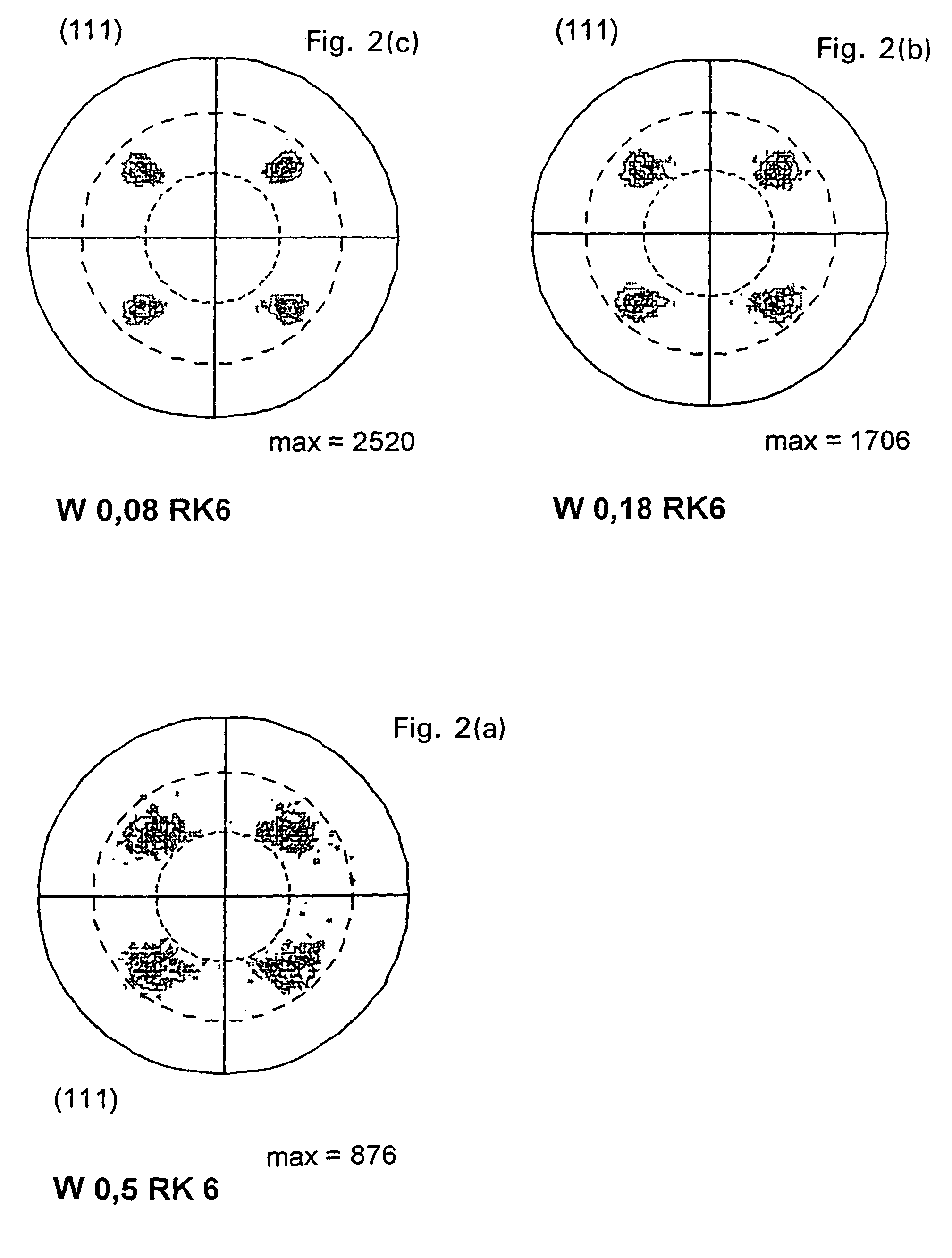
[0040]Technically pure nickel with a degree of purity of 99.9 atom percent, after being cast in a copper mold with a cross-section of about 40 mm×40 mm, is reworked by chip removal, then hot rolled to 20 mm×20 mm and annealed at 1050° C. to homogenize it. In order to provide a finely-grain structure, a 10 mm×10 mm cross-section is cold rolled and annealed so as to recrystallize it. From a thickness of 10 mm, the sample is slide drawn to a thickness of 2.5 mm. This is followed by cold conversion by roll drawing to a final thickness of 0.25 mm. A heat treatment at 800° C. follows in order to produce the high-grade cubic texture in the nickel strip.

example 3

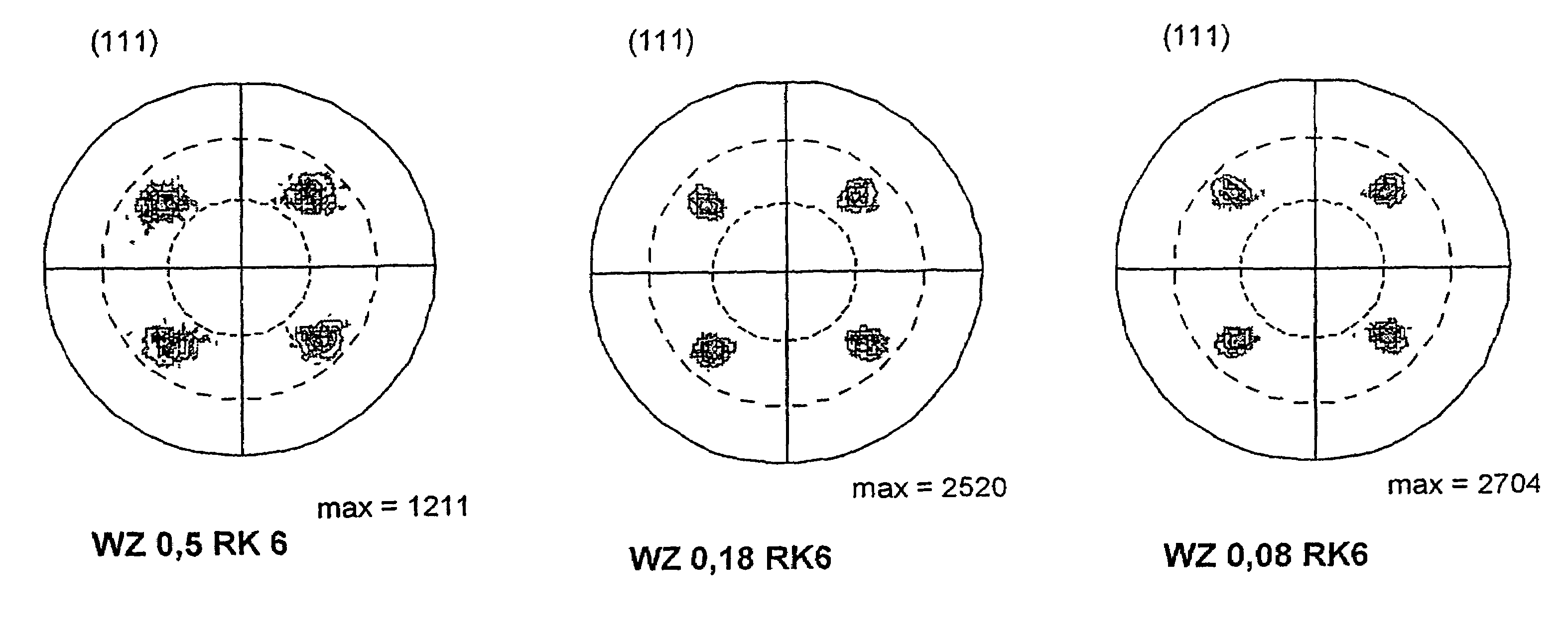
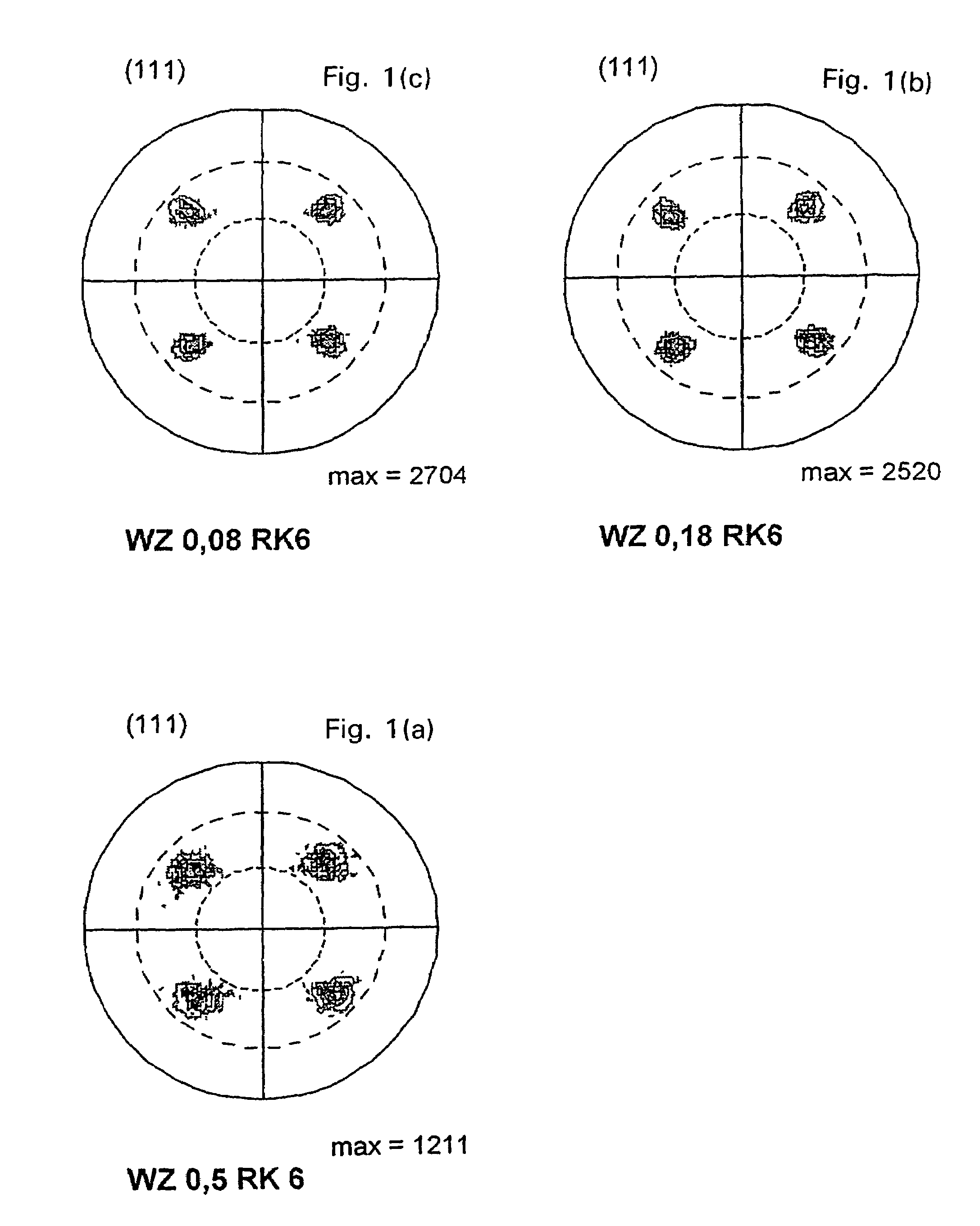
[0041]A nickel alloy, containing 5 atom percent of tungsten, is cold rolled from a cross-sectional dimensions of 20×20 m2 to a thickness of 3 mm and recrystallized at 850° C. in order to produce a finely crystalline structure. A thickness of 3 mm is roll drawn to a thickness of 0.15 mm and annealed at 1000° C. to achieve a high-grade cubic texture. It is, however, also possible to carry out the roll drawing only to 0.20 mm thickness and to undertake the final rolling to 0.15 mm with polished rollers, in order to achieve the highest possible surface quality of the strip with minimum roughness.

example 4

[0042]After an initial annealing, copper sheet, 10 mm thick, is cold drawn to the final thickness dimension of 0.08 mm through freely rotatable rolls in order to produce a soft structure. During the subsequent 30-minute heat treatment at 400° C., a sharp cubic texture is formed in the strip material.


PUM

PropertyMeasurementUnit
Fractionaaaaaaaaaa
Fractionaaaaaaaaaa
Thicknessaaaaaaaaaa

Abstract

A method for producing metallic strips having a high-grade cube texture based on nickel, copper, aluminum, silver or alloys of these metals including austenitic iron-nickel alloys makes it possible to obtain, during a subsequent annealing process and with lower total degrees of forming, a recrystallization cube layer of a quality equal to that of one obtained using customary roll forming and produces a better quality cube texture with comparable total degrees of forming. To this end, a forming method is provided during which the materials are formed by cold drawing before their recrystallization annealing thereby rendering them high-grade. The tools used for this include: a) non-driven roll devices with an axially parallel flat pair of rolls or turk's head arrangements with two pairs of rolls or; b) fixed drawing jaws that are slanted toward one another. The strips produced according to the invention can be used, for example, as a coating support for producing strip-shaped high-temperature superconductors.

Description

BACKGROUND OF THE INVENTION[0001]The invention relates to a method for producing metallic strips based on nickel, copper, aluminum, silver or the alloys of these metals, which have a high-grade annealed texture with a cubic layer.[0002]Basically, the method can be applied to all metallic materials, which tend to form the cubic texture after cold or hot drawing and a subsequent recrystallization. These include the metallic materials with cubic, face-centered lattices, such as nickel, copper, gold and, under special conditions, silver as well as a portion of their alloys, including the austenitic Fe-Ni alloys. One the other hand, this applies to aluminum after it is hot drawn by rolling.[0003]The strips, prepared according to the new method, can be used, for example, as a backing for physical / chemical coatings with a high-grade microstructural alignment. In this connection, the texture serves as a base for a crystallographically oriented growth of the deposited layers on the substrate...

Claims


Application Information

Patent Timeline
IPC IPC(8): C22F1/04C22F1/08C22F1/10C22F1/14C22F1/16B21C1/00B21C1/02B21C1/16B21C37/02H01L39/24
CPCB21C1/003B21C37/02B21C1/02H01L39/2454H10N60/0576B21C1/00H10N60/01
Inventor EICKEMEYER, JOERGSELBMANN, DIETMAROPITZ, RALPH
Owner INST FUER FESTKOERPER & WERKSTOFFORSCHUNG DRESDEN EV
Why Eureka
Try Eureka