Three-dimensional recording and reproducing apparatus
a three-dimensional recording and reproducing technology, applied in the field of optical information recording/reproducing apparatus, can solve the problems of limiting the size of information recording media, such as a disc, and the two-dimensional approach to high density will reach its limit, and the method of independent recording of binary information is not disclosed
- Summary
- Abstract
- Description
- Claims
- Application Information
AI Technical Summary
Benefits of technology
Problems solved by technology
Method used
Image
Examples
first embodiment
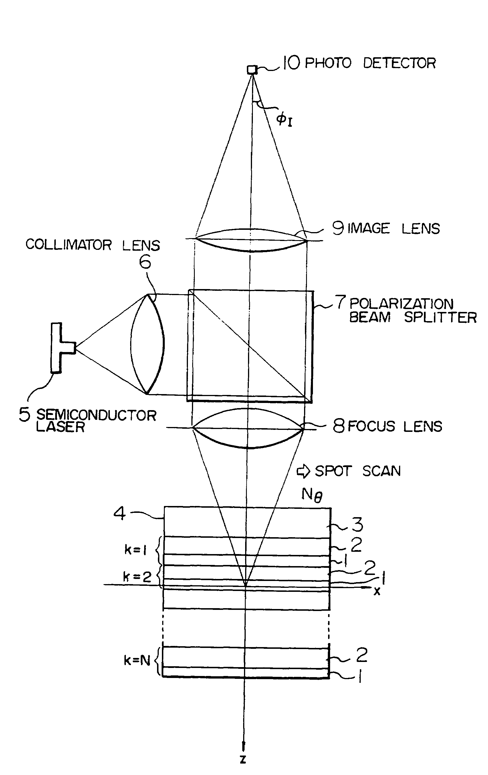
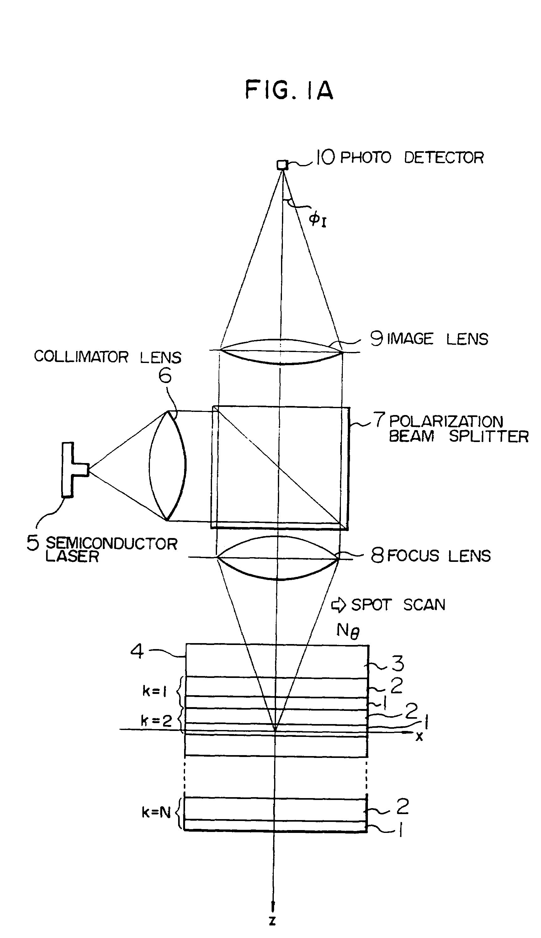
[0193]FIG. 23 shows a block diagram of the first embodiment when a target kth layer is accessed. For the rotating disc 4, a saw-tooth wave 106 is generated by an AF (autofocus) actuator shift signal generating circuit 93 to drive an AF actuator driver 91, thus shifting the focus lens 8 in the +Z direction (direction in which the lens is approached to the disc) with respect to the disc plane. At this time, an AF detecting circuit 89 generates the AF error signal 35. From this signal, the zero-cross point 105 is detected by a withdraw point determination circuit 92, thereby informing an AF servo system controller 99 of a focused point on the surface of a certain recording layer. The determination circuit generates an AF pulse 37 as shown in FIG. 24B by a slice level 37 which is slightly shifted from a zero slice level, and a falling edge of the AF pulse 37 is detected to supply the controller 99 with a timing immediately before the lens 8 passes a focused point.
[0194]The controller 99...
second embodiment
[0196]FIG. 25 shows a block diagram of a second embodiment when a kth target layer is accessed.
[0197]A focus lens 8 is raised or lowered relative to a rotating disc 4. At this time, the foregoing AF error signal is generated. Also, a total light amount 36 detected by a photo detector 10 and outputted from a total light amount detecting circuit 102 has a peak value when the focus is placed on each recording layer, as shown in FIG. 24A. Therefore, a pulse generating circuit 98 in a cross layer signal detecting circuit 101 detects an AF pulse 37 and a total light amount pulse 38 by slice levels 103, 108, and the total light amount pulse 38 is used as a gate to detect falling edges of the AF pulse, thereby further reliably detecting a focused point. Moreover, to recognize the direction in which the lens is shifted relative to the disc, the cross layer pulse generator 99a generates from these two kinds of pulses an up pulse Pa 109 and a down pulse Pb 110 which are counted to always recog...
PUM
 Abstract
Description
Claims
Application Information
 - R&D
- Intellectual Property
- Life Sciences
- Materials
- Tech Scout
- Unparalleled Data Quality
- Higher Quality Content
- 60% Fewer Hallucinations
Browse by: Latest US Patents, China's latest patents, Technical Efficacy Thesaurus, Application Domain, Technology Topic, Popular Technical Reports.
© 2025 PatSnap. All rights reserved.Legal|Privacy policy|Modern Slavery Act Transparency Statement|Sitemap|About US| Contact US: help@patsnap.com


