Method and apparatus for peak compensation in an optical filter

a technology of optical filters and peak compensation, applied in the direction of optical radiation measurement, instruments, spectrometry/spectrophotometry/monochromators, etc., can solve the problems of reducing the practical efficiency, obscuring the real signal, and uniform background signal

Active Publication Date: 2007-10-23
CHEMIMAGE TECH LLC
View PDF25 Cites 12 Cited by
  • Summary
  • Abstract
  • Description
  • Claims
  • Application Information

AI Technical Summary

Problems solved by technology

Practical efficiency is reduced due to scattering losses, imperfect spectrometer action, absorption losses in polarizing optics, etc.
Experiments with certain LCTF devices show complicated interactions arising in the material and structure of the imaging devices produce a spatial and spectral modulation of light coming through the imaging device.
The modulation produces an apparent background signal that is not uniform and masks the real signal.
It has been found that the room temperature can cause a band pass shift in the wavelength of the collected scattered photons thereby masking the Raman signal or resulting in an inaccurate as the Raman signal.
Because the ability to detect Raman vibrational features on a uniform background is critical to identifying small signal levels, the background noise can have a detrimental affect on the spectral detection.

Method used


Image

  • Method and apparatus for peak compensation in an optical filter
  • Method and apparatus for peak compensation in an optical filter
  • Method and apparatus for peak compensation in an optical filter

Examples


Embodiment Construction

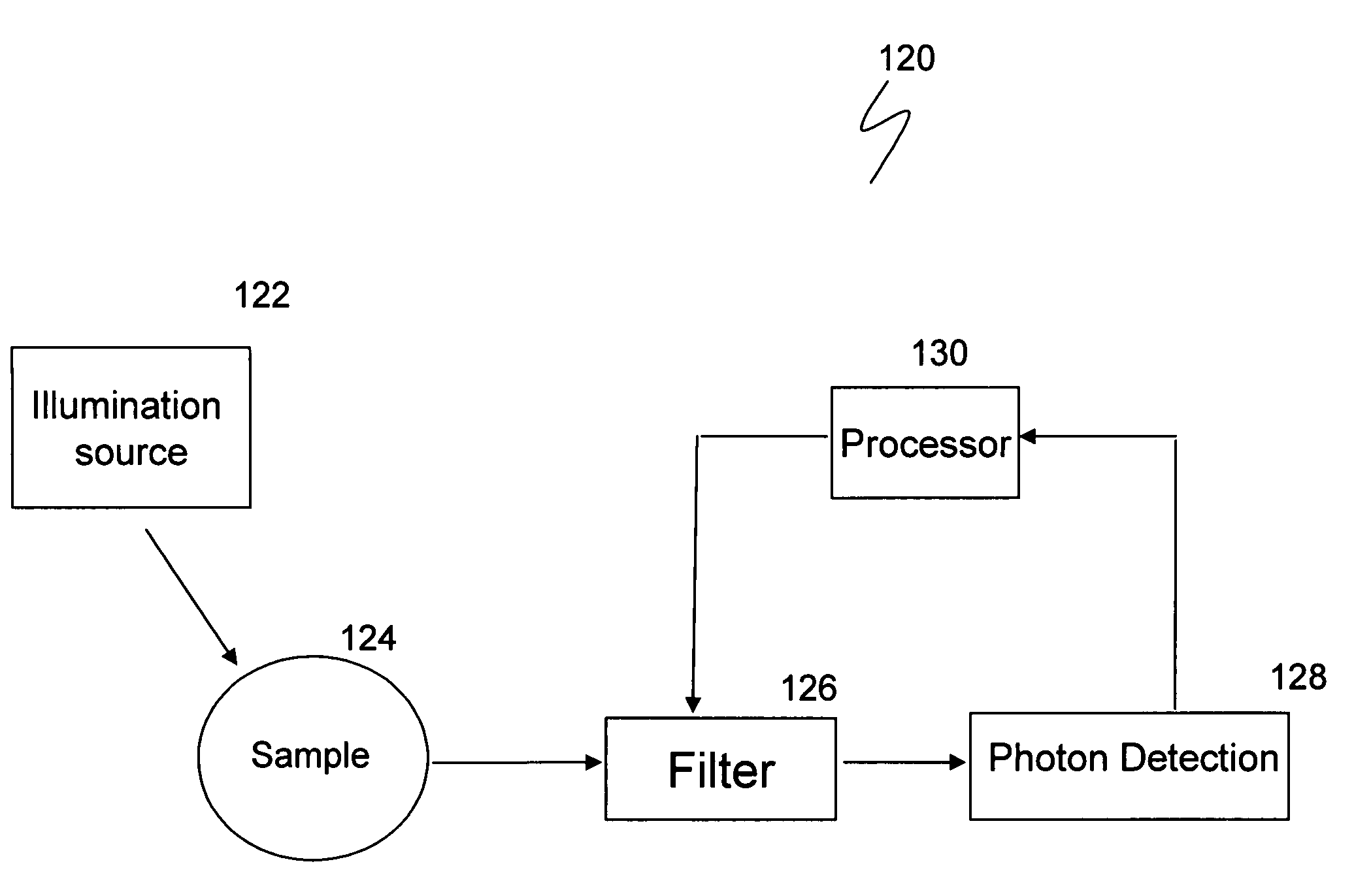
[0024]The embodiments disclosed herein enable more accurate detection and clearer images from spectroscopic imaging than conventionally possible. Application of Raman spectroscopy with certain biomedical samples including cells, tissues, bacteria, viruses and other biological entities are temperature sensitive. The embodiments disclosed herein enable detecting such samples while considering the temperature effects on the LCTF.

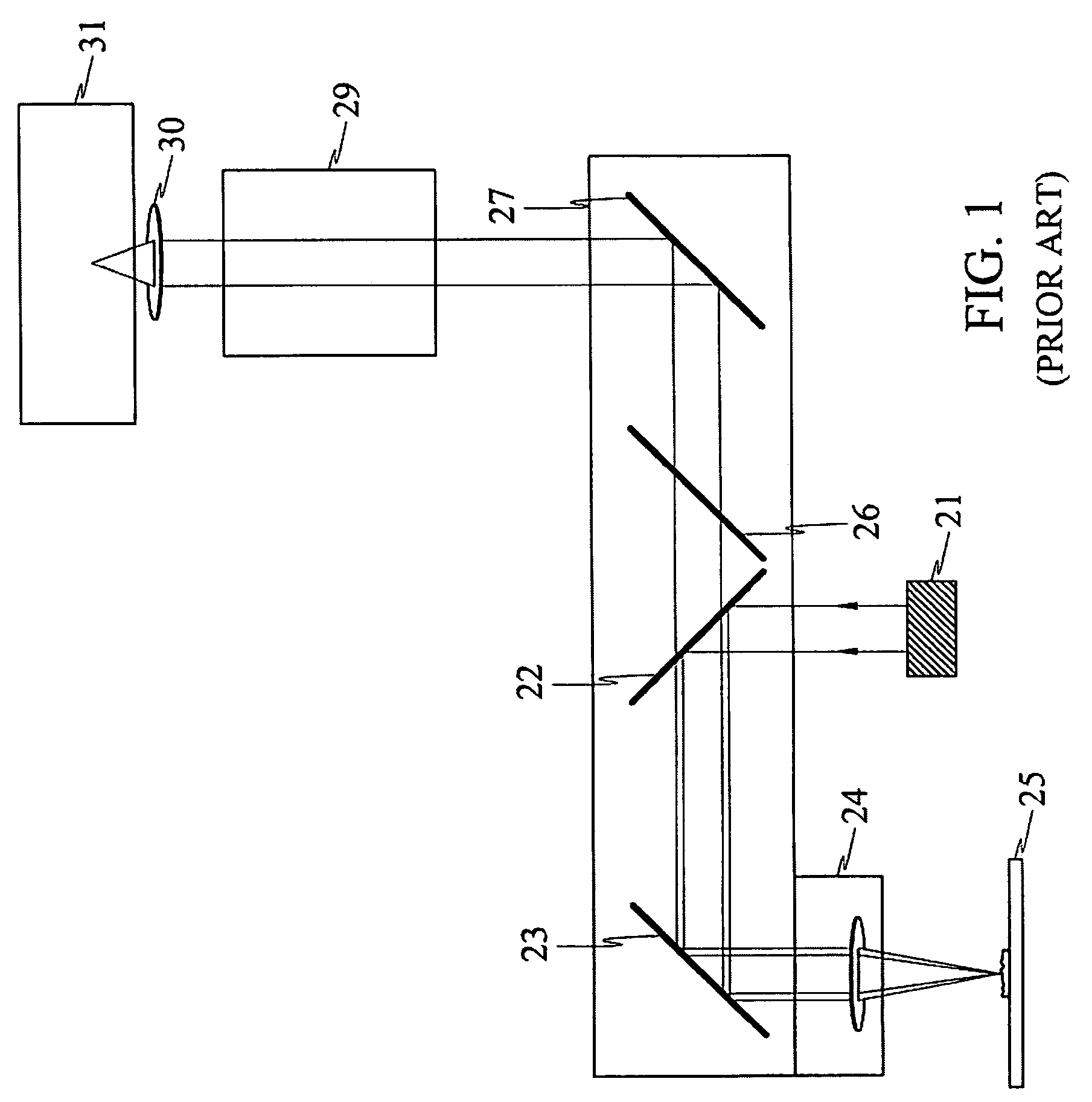
[0025]Virtually all spectral imaging filters such as AOTF, LCTF, AOF depend on the optical properties and transmission of light through one or more optical devices in order to produce the desired filtering effect. The filters have complex internal configuration which affects transmission of light through the device. It has been found that the filter performance is highly temperature dependent. Although the imaging filters are designed to minimize such aberrations, residual effects remain which limit the use of these filters for sensitive applications.

[0026]FIG....


PUM

PropertyMeasurementUnit
transmittanceaaaaaaaaaa
temperaturesaaaaaaaaaa
wavelengthaaaaaaaaaa

Abstract

In one embodiment the disclosure relates to a method and a system for determining the corrected wavelength of a photon scattered by a sample. The method includes the steps of determining a wavelength of a photon scattered from a sample exposed to illuminating photons and passed through a tunable filter and correcting the determined wavelength of the photon as a function of the temperature of the tunable filter and as a function of the bandpass set point of the tunable filter. The step of correcting the determined wavelength can further include determining an offset and adding the offset to the determined wavelength of the photon.

Description

[0001]The instant specification relates to application Ser. Nos. 10 / 879,663 and 10 / 879,632 filed concurrently herewith and entitled, respectively, System and Method for Spectroscopy and Imaging and Method and Apparatus for Spectral Modulation Compensation. Each of said applications is incorporated herein in its entirety for background information. background information.BACKGROUND[0002]Spectroscopic imaging combines digital imaging and molecular spectroscopy techniques, which can include, Raman scattering, fluorescence, photoluminescence, ultraviolet, visible and infrared absorption spectroscopies. When applied to the chemical analysis of materials, spectroscopic imaging is commonly referred to as chemical imaging. Instruments for performing spectroscopic (i.e. chemical) imaging typically comprise image gathering optics, focal plane array imaging detectors and imaging spectrometers.[0003]In general, the sample size determines the choice of image gathering optic. For example, a micro...

Claims


Application Information

Patent Timeline
Patent Type & Authority Patents(United States)
IPC IPC(8): G01J3/51G01N21/65
CPCG01J3/28G01J3/0227G01J3/027G01J3/44G01J3/0286
Inventor MAIER, JOHN S.NEISS, JASON H.STEWART, SHONA
Owner CHEMIMAGE TECH LLC
Why Eureka
Try Eureka