Molded laminate for optical use

a technology of optical use and molded laminate, which is applied in the field of molded laminate for optical use, can solve the problems of inability to mix inorganic photochromic compound with plastic lens materials to produce transparent lenses, and is less effective in protecting eyes, and achieves the effect of high degree of polarization and small quantity production

Inactive Publication Date: 2007-10-30
NAKAGOSHI YASUNOBU
View PDF13 Cites 24 Cited by
  • Summary
  • Abstract
  • Description
  • Claims
  • Application Information

AI Technical Summary

Benefits of technology

[0022]The molded laminate for optical use made according to the present invention is characterized by its transparency and high degree of polarization. Furthermore, by the use of an adhesive with a organic photochromic compound mixed therein for bonding the cellulose triacetate film providing a convex surface for the resultant hot-bent molded laminate, molded laminates having different colors and/or different depths can be economi

Problems solved by technology

However, because these lenses are made of glass, they are easy to break and heavy, so that they are less effective in protecting eyes.
It was, however, impossible to mix an inorganic photochromic compound with plastic lens materials to produce transparent lenses.
In order to provide sufficient photochromism to the coating, it is necessary to add a considerable amount of an organic photochromic compound to the coating material, which may reduce scratch-preventing ability desired for the coating and may reduce adhesion of the coating to the lens base.
A major constituent of most of the resin materials cast shown in this publication low-cost vinyl monomer, and, therefore, the strength of the resulting lenses is too small to protect eyes.
They are weak against shock and, therefore, easily broken.
In addition, such material requires a large amount of organic photochromic compound to be added, which results in high costs of the resultant products.
Recently, lenses made by casting urethane prepolymer which are hard to crack are available, but urethane prepolymer requires a curing time four or five times as long as that of vinyl monomer resins, which means that the productivity of urethane prepolymer lenses is low, and, therefore, the costs of urethane prepolymer lenses are very high.
The optical surface accuracy of the laminate sheet

Method used


Image

  • Molded laminate for optical use
  • Molded laminate for optical use

Examples


example 1

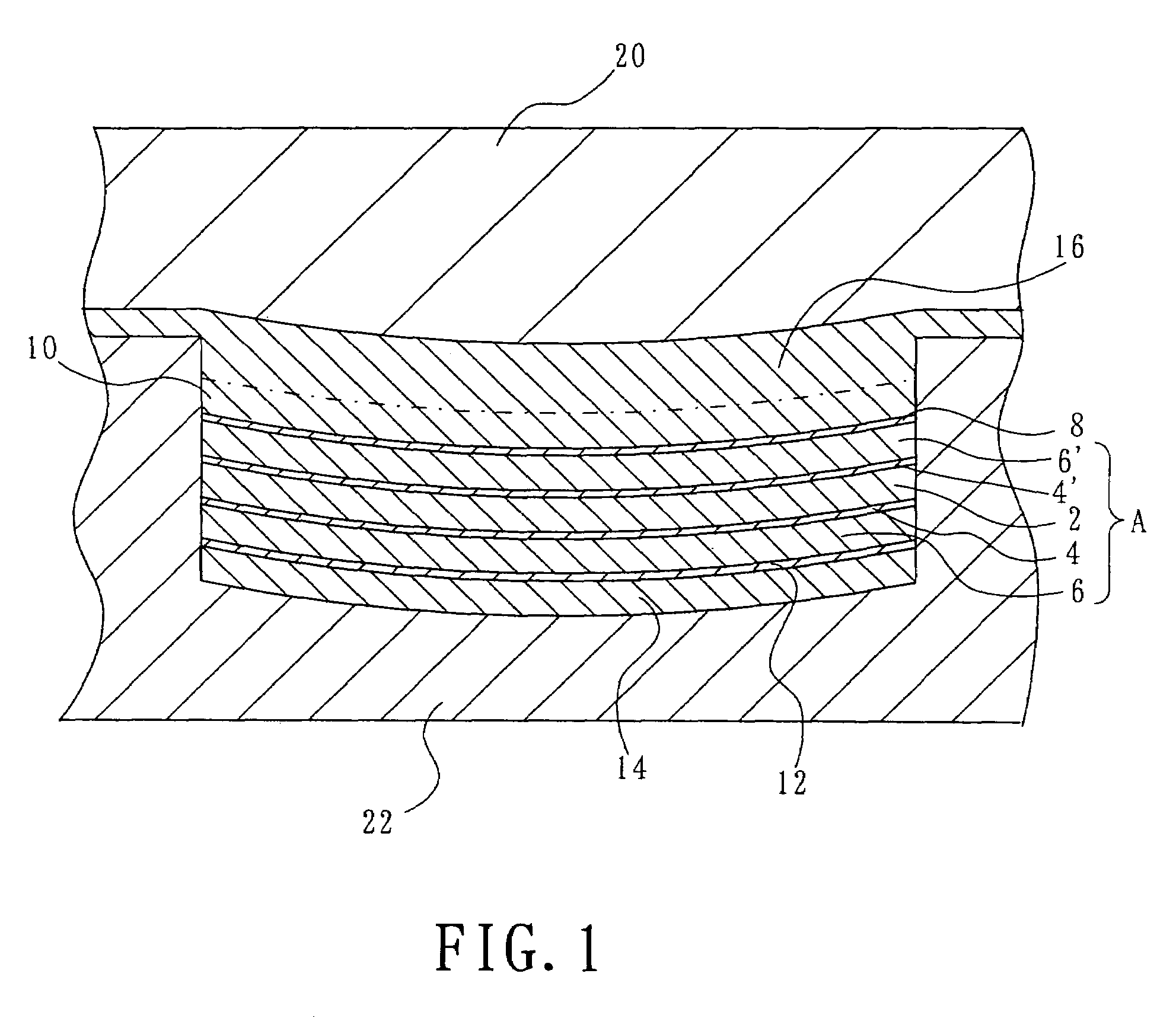
[0039]A polarizing sheet available from Sumitomo Chemical Company, Limited, known as SUMIKALAN® SQ-1852A, having a thickness of 0.18 mm and a light transmissivity of 43.7%, was used. The polarizing sheet includes first and second cellulose triacetate films each having a thickness of 0.08 mm onto the respective opposing surfaces of a polarizing film of polyvinyl alcohol dyed with an iodine-type dye stuff. The polarizing film has a thickness of 0.02 mm and a degree of polarization of 99.95%. A polycarbonate resin film having a thickness of 0.15 mm and having a light transmissivity of 89%, which is compatible and fusible with a lens molding polycarbonate resin, was bonded to the exposed surface of the first cellulose triacetate film of the polarizing sheet, using a two-component type polyurethane resin as the adhesive.

[0040]Then, a third cellulose triacetate film, which was free of an ultraviolet absorber and had a thickness of 0.05 mm, was bonded to the exposed surface of the second c...

example 2

[0043]A polyallylate film, which had a thickness of 0.14 mm, exhibited a light transmissivity of 88%, and was compatible or fusible with a lens molding polyallilate resin, was bonded to the exposed surface of the first cellulose triacetate film of the same polarizing sheet as used in Example 1, by the use of a two-component polyether polyurethane resin adhesive.

[0044]Then, over the exposed surface of the second cellulose triacetate film, an adhesive was applied to a thickness of 0.01 mm, by means of which a third cellulose triacetate film free of an ultraviolet absorber having a thickness of 0.05 mm was bonded to the second cellulose triacetate film to thereby obtain a laminate sheet. The adhesive used to bond the third cellulose triacetate film to the second one was a two-component type polyester polyurethane resin to which 1.5% by weight, to the solid content of the two-component type polyester polyether resin, of the following was added:

1-(2-methoxy-5-nitrobenzyl)-3,3-dimethylspi...

example 3

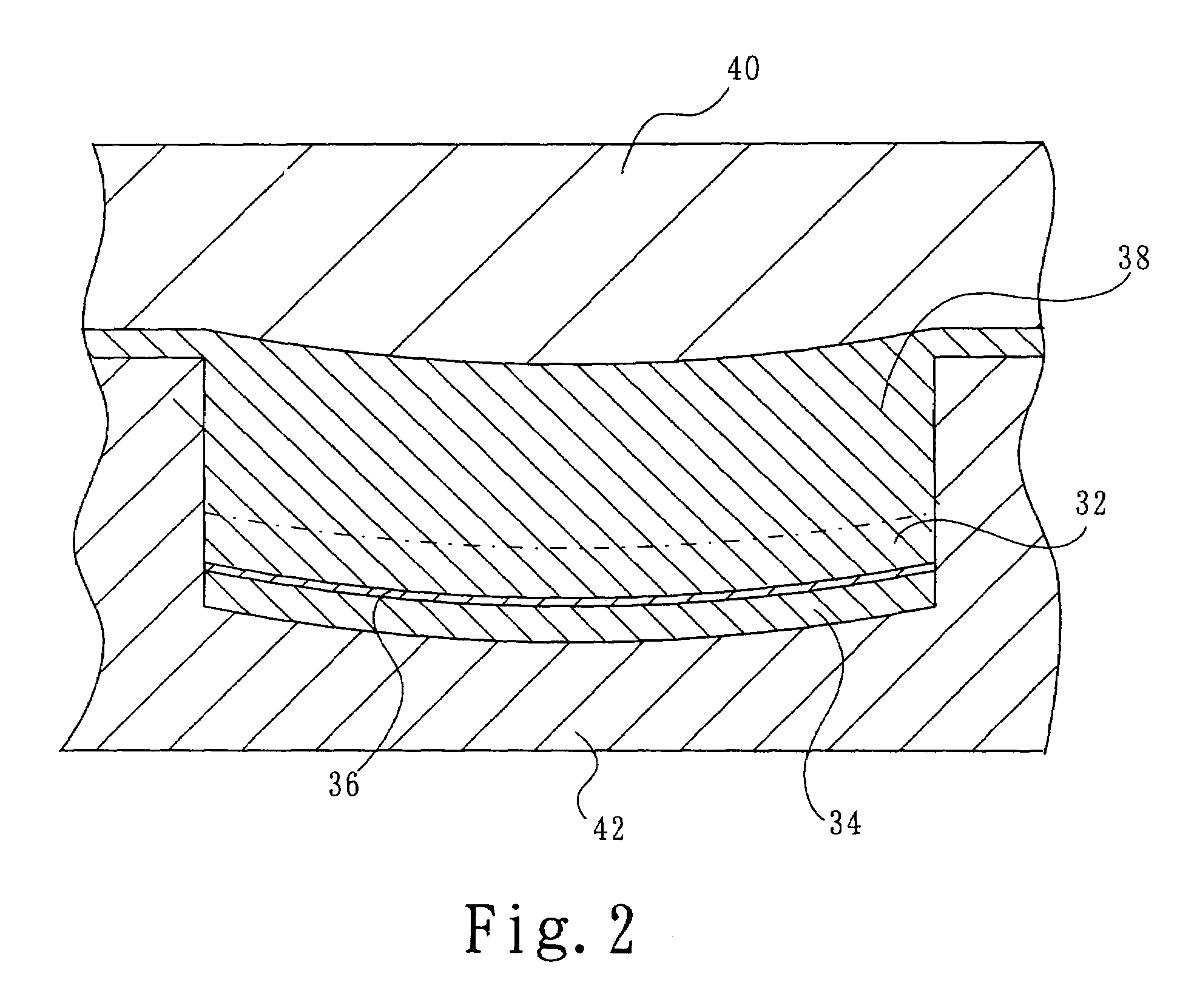
[0046]A polycarbonate resin and a polybutylene terephthalate were uniformly blended in a weight ratio of 60:40, from which a transparent thermoplastic film having a thickness of 0.2 mm was prepared. Over the thus prepared transparent plastic film, the two-component type polyether polyurethane adhesive containing the photochromic compound same as used in Example 1 was applied to a thickness of 0.02 mm, over which a cellulose triacetate film free of an ultraviolet absorber having a thickness of 0.05 mm was placed to form a laminate sheet.

[0047]The laminate sheet was subjected to hot bending to a shape in which the exposed cellulose triacetate film exhibited convexity, while the exposed surface of the thermoplastic film exhibited concavity. The hot-bent laminate sheet was placed in an injection mold, and the same resin as the thermoplastic film was injected over the exposed surface of the thermoplastic film, to thereby form an optical lens having a thickness of 2.0 mm.

[0048]The light t...


PUM

PropertyMeasurementUnit
Lengthaaaaaaaaaa
Lengthaaaaaaaaaa
Lengthaaaaaaaaaa

Abstract

A polarizing sheet (A) includes a polarizing film (2) and cellulose triacetate films (6, 6′) bonded to opposing surfaces of the polarizing film (2) with adhesive layers (4, 4′) interposed, respectively. A thermoplastic film (10) is stacked on the exposed surface of one (6′) of the cellulose triacetate films. Another cellulose triacetate film (14) free of an ultraviolet absorber is bonded to the exposed surface of the other cellulose triacetate film (6) of the polarizing sheet with an adhesive (12) containing an organic photochromic compound, to thereby form a laminate sheet. The laminate sheet is placed in an injection mold, and a molding resin material fusible with the thermoplastic film (10) is injected over the thermoplastic film.

Description

[0001]The present invention relates to a molded laminate for use in manufacturing a lens, such as a polarizing lens and a sunglass lens, which exhibits a polarization property as well as a photochromic property such as to cause the laminate to exhibit variable light transmissivity by being colored by absorbing light and losing the color when light is blocked.BACKGROUND OF THE INVENTION[0002]Recently, in the spectacle lens market, demand for lenses which can protect eyes and are friendly to eyes has increased. Many of spectacle lenses have been glass lenses, but, in these days, plastic lenses are mainly used because plastic lenses can protect eyes from accidents which would be caused by broken lenses. Further, materials of plastic lenses have been improved so that the lenses can be hardly broken.[0003]Lenses are required to have a high refractive index and be light and thin, be able to block harmful light to eyes by cutting ultraviolet rays or having a polarizing property, and have s...

Claims


Application Information

Patent Timeline
IPC IPC(8): G02F1/03
CPCB29C45/14811G02B5/3033G02C7/12G02B5/23B29C2045/14319B29L2011/0016G02F2202/14B29C2045/14237G02B5/3041
Inventor NAKAGOSHI, YASUNOBU
Owner NAKAGOSHI YASUNOBU
Why Eureka
Try Eureka