Direct drive spindle, machining center and methods of fabricating the same

Inactive Publication Date: 2007-11-13
ROUNDTOP MACHINERY IND
View PDF28 Cites 39 Cited by
  • Summary
  • Abstract
  • Description
  • Claims
  • Application Information

AI Technical Summary

Benefits of technology

[0035]It is yet another objective of the present invention to provide a vertical & horizontal machining center equip

Problems solved by technology

To such a conventional spindle head assembly with the presence of the intermediate transmission component as preciously discussed, the machining efficiency thereof can be significantly limited because the spindle head has to be slowed down from a preset cutting speed before being imparted with a currently required operational angle and then be sped up to the preset cutting speed to proceed with the machining work.
However, each the motor assembly thereof has its stator di

Method used


Image

  • Direct drive spindle, machining center and methods of fabricating the same
  • Direct drive spindle, machining center and methods of fabricating the same
  • Direct drive spindle, machining center and methods of fabricating the same

Examples


second embodiment

[0050]Please refer to FIG. 5 for the present invention that relates to a method for manufacturing a direct drive spindle assembly, wherein the following steps are included:

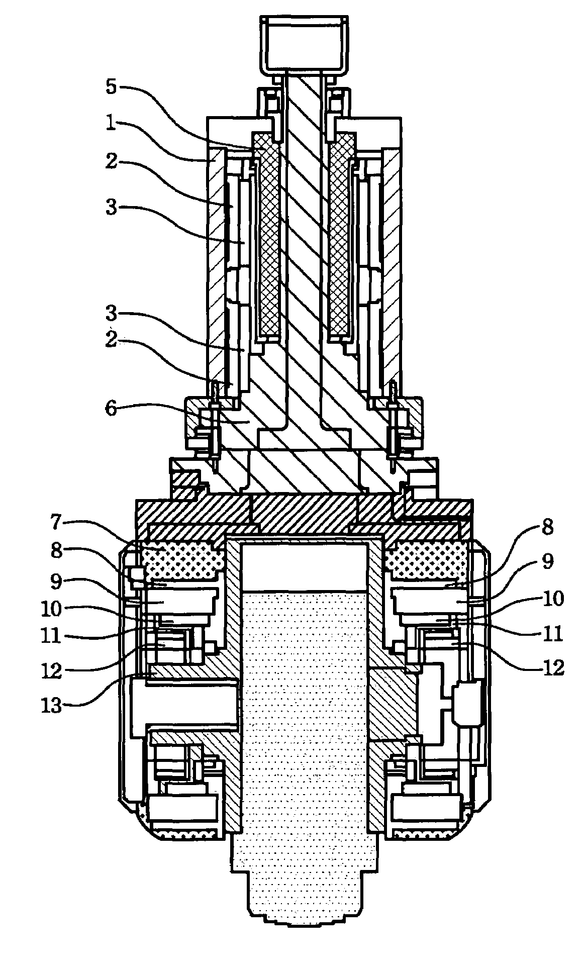
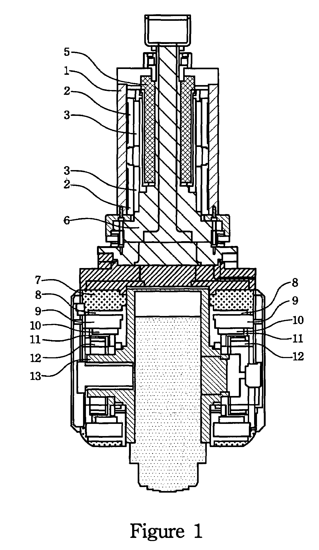
[0051]providing a main fork which is rotated about a first rotational axis and formed by a base 6 and a parallel pair of spaced fork arms 7;

[0052]providing a first drive means which is established by a hollow housing 1, a first motor stator 2 and a first motor rotor 3, wherein the first motor rotor 3 coupled with the base 6 of the main fork drives the main fork to rotate about the first rotational axis;

[0053]providing a second drive means which is contained between the fork arms 7 of the main fork and established by a second motor stator 9 concentric with a second rotational axis, a second motor rotor 10 and a rotor transmission ring 11, wherein the second rotational axis is perpendicular to the first rotational axis and the second motor stator 9 is coupled with the fork arms 7 of the main fork;

[0054]providing a s...

third embodiment

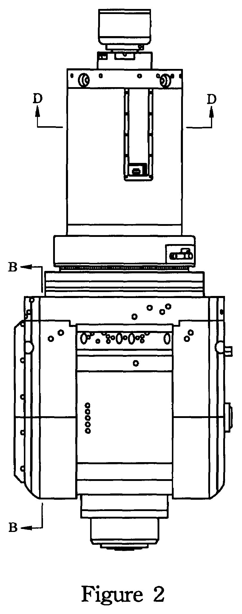
[0060]The present invention herein provides a third embodiment regarding a vertical machining center comprising a direct drive spindle assembly, which is characterized by the direct drive spindle assembly having a main fork, a first drive means, a second drive means and a spindle box 13 wherein the main fork is formed by a base 6 and a parallel pair of spaced fork arms 7 and rotated about a first rotational axis. As can be seen in FIGS. 2 and 3, the first drive means is established by a hollow housing 1 which is concentric with a first rotational axis, a first motor stator 2 and a first motor rotor 3, wherein the first motor rotor 3 coupled with the base 6 of the main fork drives the main fork to rotate about the first rotational axis. The description is now referred to FIGS. 2 and 4 wherein it can be seen that the second drive means is contained between said fork arms 7 of the main fork and established by a second motor stator 9 concentric with a second rotational axis, a second mo...

fourth embodiment

[0065]The present invention herein provides a fourth embodiment regarding a horizontal machining center comprising a direct drive spindle assembly, which is characterized by the direct drive spindle assembly having a main fork, a first drive means, a second drive means and a spindle box 13 wherein the main fork is formed by a base 6 and a parallel pair of spaced fork arms 7 and rotated about a first rotational axis. As can be seen in FIGS. 2 and 3, the first drive means is established by a hollow housing 1 which is concentric with a first rotational axis, a first motor stator 2 and a first motor rotor 3, wherein the first motor rotor 3 coupled with the base 6 of the main fork drives the main fork to rotate about the first rotational axis. The description is now referred to in FIGS. 2 and 4 where it can be seen that the second drive means is contained between said fork arms 7 of the main fork and established by a second motor stator 9 concentric with a second rotational axis, a secon...


PUM


Abstract

This invention discloses a direct drive spindle assembly including a main fork formed by a base and a parallel pair of spaced fork arms and rotated about a first rotational axis. Moreover, the direct drive spindle assembly includes a first drive established by a hollow housing, a first motor stator and a first motor rotor, wherein the first motor rotor coupled with the base of the main fork drives the main fork to rotate about the first rotational axis. Furthermore, the direct drive spindle assembly includes a second drive contained in a room between the fork arms of the main fork and established by a second motor stator concentric with a second rotational axis, a second motor rotor and a rotor transmission ring, wherein the second rotational axis is perpendicular to the first rotational axis and the second motor stator is coupled with the fork arms of the main fork. In addition, the direct drive spindle assembly includes a spindle box having an orthogonal cross structure. A first arm of the rotor transmission ring is coupled with the second motor rotor and a second arm of the structure is connected to a spindle head. The feature of the present invention is that after the second drive is fit in the room between the above-mentioned paired fork arms of the main fork and then combined with the base of the main fork and firmly locked in the right position, the whole structure can achieve preferred precision.

Description

BACKGROUND OF THE INVENTION[0001]1. Field of the Invention[0002]The present invention relates to a machining center and a method for manufacturing the same, and more particularly, to a machining center having a spindle head equipped with direct-drive transmission components.[0003]2. Description of the Prior Art[0004]According to the known technique regarding conventional multi-axis machining centers, intermediate transmission components such as a timing belt units, gear-rack units, worm-gear units, bevel gear units, spur gear units, or combinations of said units are typically implemented for operatively connecting a spindle head and a distant spindle motor which drives the spindle head. To satisfy machining requirements of complex surface structures of machine dies or aero parts, the spindle head has to be kept at a particular angle with respect to the surface being machined throughout the machining process. Once the contour variation of the surface being machined occurs, adjustment...

Claims


Application Information

Patent Timeline
IPC IPC(8): B23P15/00B23C1/12
CPCB23Q1/5406B23Q2210/004B23Q2220/006Y10T29/49904Y10T409/307672Y10T409/308512Y10T29/49826
Inventor TSAO, HSIANG-YUANLIN, CHUN-CHIEH
Owner ROUNDTOP MACHINERY IND
Why Eureka
Try Eureka